Soft Bodies
Introduction
As opposed to rigid bodies, which preserve the relative poses of their vertex representation, soft bodies support relative motion of the nodes governing their form. A consequence of this complexity is that soft bodies deform under applied force, while rigid bodies do not. PhysX soft body simulation employs a combination of FEM (Finite Element Method) and two tetrahedral meshes. The first tetrahedral mesh is a simulation mesh, which only needs to approximately match the body’s shape. This freedom allows the use of meshes with more regular and equal-sized tetrahedra. The second tetrahedral mesh is the collision mesh. The collision mesh needs to match the surface of the simulated body accurately, otherwise the collision response will not be accurate. In addition to the simulation and collision meshes, there is also an associated triangle mesh that is used for rendering. The render mesh is typically used to generate the collision mesh. To achieve a smooth deformation the render mesh should have uniformly distributed vertices.
Tet Maker
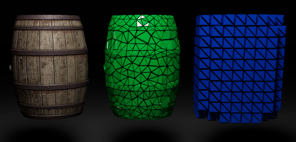
The tetrahedral meshes required to create a soft body can be provided either from an external source or they can be created directly in PhysX by a component called Tet Maker. This process can be time consuming, therefore it is recommended to do it as a preprocessing step and save the cooked meshes to a file. The collision mesh is typically created from the render mesh by calling createConformingTetrahedronMesh(…). The surface of the resulting tetrahedral mesh will exactly match the surface of the input triangle mesh. The vertex list of the collision mesh replicates all vertices from the render mesh. The mesher can append additional vertices in case this is required to generate a valid tetrahedral mesh. The simulation mesh can be created by calling createVoxelTetrahedronMesh(…) which takes the previously generated collision mesh as input as well as parameters to define the resolution of the output mesh. It will create voxels completely enclosing the collision mesh. The following image shows the render mesh, the collision tetmesh and the simulation tetmesh from left to right.
There are a few variables for users to control the resolution of the mesh and to get optional embedding information:
numVoxelsAlongLongestBoundingBoxAxis: Allows control over the resolution of the resulting mesh. The parameter specifies the number of voxels to generate along the longest axis of the input mesh’s bounding box. The number of cells along the smaller dimensions will be computed such that voxels get similar edge lengths in all directions.
numTetsPerVoxel: Every voxel will be split into 5 or 6 tetrahedra to produce a mesh with elements of similar size and shape.
inputPointToOutputTetIndex: This is an optional parameter that allows a mapping between input point and the tetrahedron containing the point. If NULL is passed in, that information is not generated, otherwise pointer to a list with size matching the number of input vertices can be provided.
The example in the section Using GPU Soft Bodies shows how to generate both meshes.
Mesh Cleaning
Some triangle meshes contain holes, self intersections, sliver triangles (triangles where at least one angle is much bigger or much smaller than the other angles) or other defects. Generating a tetmesh out of a triangle mesh that has defects might not be possible or lead to a bad tetmesh. In that case a remeshing operation can help to fix the mesh defects. Other triangle meshes might simply have an excessive amount of triangles such that it makes sense to reduce the mesh’s resolution before generating a collision and a simulation tetmesh. The high resolution triangle mesh can still be used for rendering.
The following piece of code shows how to create a new set of vertices and triangles using a remeshing operation to fix mesh defects:
PxArray<PxVec3> inputVertices;
PxArray<PxU32> inputIndices;
PxArray<PxVec3> outputVertices;
PxArray<PxU32> outputIndices;
PxI32 remesherGridResolution = 100;
PxTetMaker::remeshTriangleMesh(inputVertices, inputIndices, remesherGridResolution, outputVertices, outputIndices);
A remeshing operation might increase the number of triangles. This depends on the resolution of the internal grid that the remesher uses. In many cases it makes sense to reduce the number of triangles to a number that still captures the mesh’s surface well while being as low as possible because the less triangles, the less tetrahedra the collision tetmesh will have and the faster the simulation will run. The following code shows how to reduce the number of triangles in a mesh to a given target. It does not make use of the maximal edge length feature that allows to avoid too long triangle edges because big triangles don’t approximate the body’s shape well when it starts deforming:
PxArray<PxVec3> inputVertices;
PxArray<PxU32> inputIndices;
PxArray<PxVec3> outputVertices;
PxArray<PxU32> outputIndices;
PxI32 targetTriangleCount = 500;
PxReal maximalTriangleEdgeLength = 0.0f;
PxTetMaker::simplifyTriangleMesh(inputVertices, inputIndices, targetTriangleCount, maximalTriangleEdgeLength, outputVertices, outputIndices);
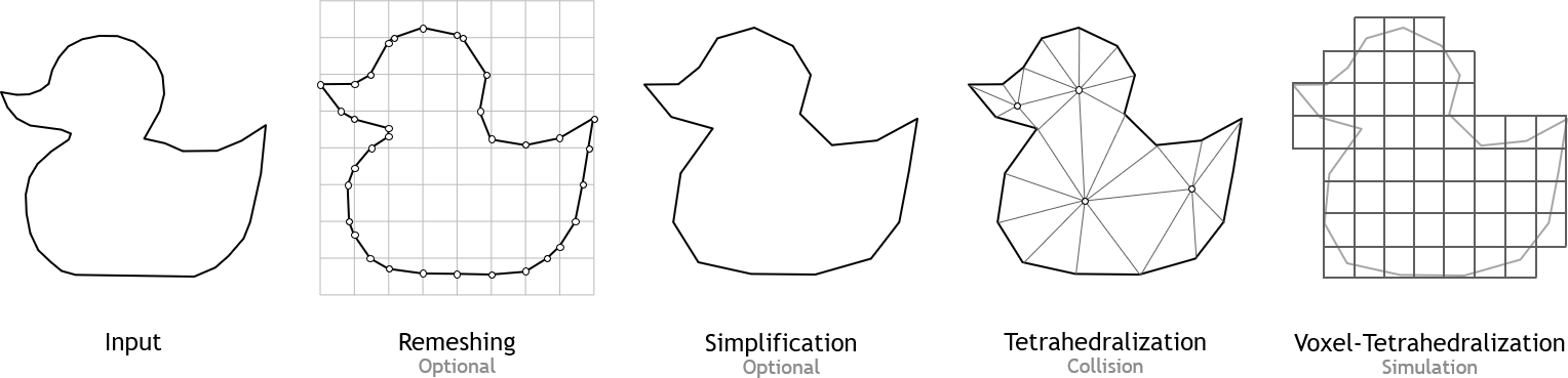
All mesh processing steps are usually performed in the following order
Remeshing (optional)
Mesh Simplification (optional)
Creation of collision tetmesh
Creation of simulation tetmesh using the voxel tetmesher
Cooking
During the cooking process, all internal structures required by the simulation are configured. This includes acceleration structures for collision detection; ordering and partitioning for the tetrahedra mesh; mass/volume properties for every vertex/tetrahedra of the simulation mesh; and remap tables to update the collision mesh’s vertices according to the simulation mesh’s deformation. This precomputed data must be updated if the topology of the soft body is changed by the application at runtime e.g. due to tearing/cutting. Density, uniform scaling and translation are defined when the softbody is constructed.
Depending on the mesh’s resolution, cooking might take some time. To avoid calculating this data every time a simulation starts, the cooked data can be saved to a file by calling cookSoftbodyMesh. To load the cooked file, the PxPhysics instance provides a createSoftbodyMesh method that takes a file stream as source:
//Cook and save the mesh
PxDefaultFileOutputStream writeBuffer(cacheFilename);
bool status = PxCookSoftBodyMesh(cookingParams, simMeshDesc, meshDesc, simDesc, writeBuffer);

//Load the cooked mesh
PxDefaultFileInputData readBuffer(cacheFilename);
tetMesh = getPhysics().createSoftbodyMesh(readBuffer);
Using GPU Soft Bodies
PhysX soft bodies are currently only supported on GPU. This feature is implemented in CUDA and requires a compatible GPU. If no compatible device is found, an error message will be displayed. The following snippet shows how to create a softbody from scratch given only triangle mesh vertices and indices. Separate collision and simulation meshes are used in the snippet. It is also possible to use the same mesh as simulation and collision mesh:
//Compute collision mesh
physx::PxArray<physx::PxVec3> collisionMeshVertices, simulationMeshVertices;
physx::PxArray<physx::PxU32> collisionMeshIndices, simulationMeshIndices;
PxTetMaker::createConformingTetrahedronMesh(surfaceMesh, collisionMeshVertices, collisionMeshIndices);
PxTetrahedronMeshDesc meshDesc(collisionMeshVertices, collisionMeshIndices);

//Compute simulation mesh
PxU32 numVoxelsAlongLongestAABBAxis = 20;
physx::PxArray<physx::PxI32> vertexToTet;
vertexToTet.resize(meshDesc.points.count);
PxTetMaker::createVoxelTetrahedronMesh(meshDesc, numVoxelsAlongLongestAABBAxis, simulationMeshVertices, simulationMeshIndices, vertexToTet.begin());
PxTetrahedronMeshDesc simMeshDesc(simulationMeshVertices, simulationMeshIndices);
PxSoftbodySimulationDataDesc simDesc(vertexToTet);

PxSoftbodyMesh* mesh = PxCreateSoftBodyMesh(cookingParams, simMeshDesc, meshDesc, simDesc, getPhysics().getPhysicsInsertionCallback());

PxSoftBody* softBody = getPhysics().createSoftBody();
softBody->setCudaContextManager(mCudaContextManager);
PxShapeFlags shapeFlags = PxShapeFlag::eVISUALIZATION | PxShapeFlag::eSCENE_QUERY_SHAPE | PxShapeFlag::eSIMULATION_SHAPE;
PxFEMSoftBodyMaterial* materialPtr = getPhysics().createFEMSoftBodyMaterial(1e+9f, 0.45f, 0.5f);
PxTetrahedronMeshGeometry geometry(mesh->getCollisionMesh());
PxShape* shape = getPhysics().createShape(geometry, &materialPtr, 1, true, shapeFlags);
softBody->attachShape(*shape);
softBody->attachSimulationMesh(*mesh->getSimulationMesh(), *mesh->getSoftBodyAuxData());
getActiveScene().addSoftBody(*softBody);
In addition to the softbody geometry, a few solver settings should be configured. The section about tuning provides more details:
PxShape* shape = softBody->getShape();
shape->setSoftBodyMaterials(&femMaterial, 1);
softBody->setParameter(femParams);
softBody->setSolverIterationCounts(iterCount);
To adjust location, orientation and scaling of a softbody after cooking, an optional call to transform will modify the internal softbody buffers accordingly:
PxSoftBodyExt::transform(*softBody, transform, scale);
The maximal inverse mass Ratio specifies how much the mass at connected vertices is allowed to vary. Bit mass ratios in the mesh can be bad for the simulation stability and convergence. To ensure that the body has a properly defined mass, either total mass or mass density must be specified:
PxSoftBodyExt::setMass(*softBody, mass, maxInvMassRatio);
Alternatively, the body’s mass can be defined by calling updateMass, which takes a density parameter as argument:
PxSoftBodyExt::updateMass(*softBody, density, maxInvMassRatio);
Finally, the softbody buffers need to be uploaded to the GPU. This can either be done by calling writeData on the softbody for every buffer to upload or more easily using the commit method from the softbody extensions:
PxSoftBodyExt::commit(*softBody, PxSoftBodyData::eALL);
Soft Body direct API
The direct API for softbodies allows access to the GPU buffers of one or multiple softbodies. To improve performance of the data copies, buffers of multiple softbodies can be read or written with a single call, which is particularly beneficial for scenes with many small softbodies. The direct API’s main purpose is to support data transfers between GPU buffers to avoid copying data to the CPU. It can be accessed through the methods copySoftBodyData and applySoftBodyData, which are part of the PxScene class.
copySoftBodyData can be used to copy softbody data from one or multiple GPU buffers into other GPU buffers. Acceptable buffer types are GPU buffers or mapped CPU buffers. For best performance, it is recommended to work exclusively with GPU buffers:
void copySoftBodyData(void** data, void* dataSizes, void* softBodyIndices, PxSoftBodyDataFlag::Enum flag, const PxU32 nbCopySoftBodies, const PxU32 maxSize, void* copyEvent = NULL);
To modify the softbodies, applySoftBodyData will apply the data provided:
void applySoftBodyData(void** data, void* dataSizes, void* softBodyIndices, PxSoftBodyDataFlag::Enum flag, const PxU32 nbUpdatedSoftBodies, const PxU32 maxSize, void* applyEvent = NULL);
Both methods share the following argument list:
data: A cuda array that holds pointers to target or source GPU buffers, one for each softbody to apply/copy data.
dataSizes: A cuda array with the size of every buffer in bytes.
softBodyIndices: A cuda array with the indices of the softbodies that are part of the transaction. This allows copy operations to be selectively applied to a subset of softbodies.
flag: The type of buffer that should be copied/applied, e. g. vertices, restPoses etc.
nbSoftBodies: The number of softbodies taking part in the transaction.
maxSize: The maximum size in bytes of all of the softbody data buffers that take part in the transaction.
event: A cuda event that can be used for synchronization.
Tuning
The deformation behavior of a softbody is controlled through its material (PxFEMMaterial). One material property is Young’s Modulus, a measure of body stiffness. Its value will depend on the scale unit used by the meshes. Volume preservation is controlled through the Poisson’s Ratio. A value of 0.5 describes a fully incompressible material. The Poisson’s Ratio must be chosen < 0.5 because a value of exactly 0.5 might lead to numerical problems. A typical value is 0.45. Another important material property is the damping value. If set to zero, no damping will be applied.
Performance Considerations
To improve performance, it is advisable to choose tetrahedral meshes with the lowest resolution that delivers satisfactory results. At each simulation timestep, a stress measure is evaluated for each tetrahedron. The resolution of a mesh, therefore, has a direct impact on the computational effort required to update the deformation. Very stiff models often require more solver iterations to converge. Using a lower resolution simulation mesh often helps to simulate stiff objects, while keeping the required number of iterations low. To reduce the number of tetrahedra it is worth considering a collision mesh with very few interior nodes.