CAD to USD#
A step-by-step guide for converting CAD data to USD format for digital twin and virtual facility applications.
Overview#
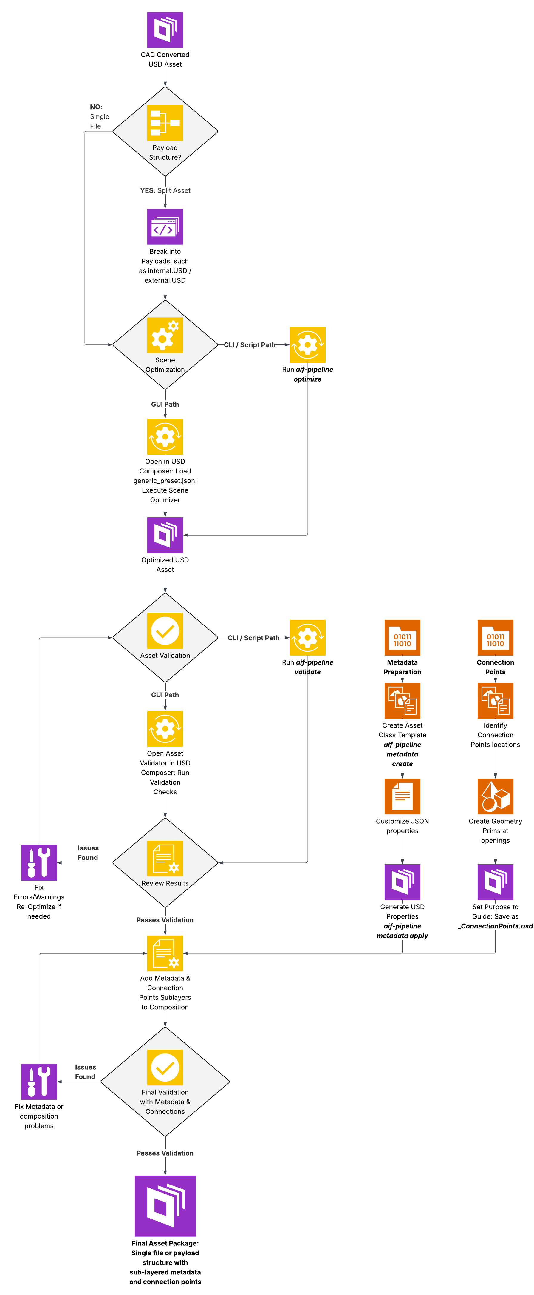
This workflow transforms CAD data into optimized, validated USD assets suitable for digital twin and virtual facility applications. The process consists of five main stages:
CAD Conversion - Transform CAD files to USD format
Validation - Ensure asset quality and standards compliance
Optimization - Enhance performance, quality, and compliance
Metadata Application - Add semantic information and properties
Connection Definition - Define facility connection points for simulation
In this sample, each step can be performed through GUI tools in NVIDIA Omniverse or CLI tools that use the same underlying SDKs and APIs for automation and batch processing.
The CLI tools include individual Python scripts (cad_convert.py, validate.py, optimize.py) for direct execution. A unified command-line interface (aif-pipeline) wraps these scripts with consistent commands and config-driven settings.
Prerequisites#
Before starting the workflow, complete Setup:
USD Composer - Install using Setup Option 1 or Option 2
aif-pipeline CLI - Install and configure per the setup guide (Python 3.10-3.12 is handled automatically by
uv sync)
Verify your setup:
aif-pipeline --help
aif-pipeline config show
Note
The CLI wraps Python scripts in scripts/ (cad_convert.py, validate.py, optimize.py). Refer to Scripts for direct usage if needed.
Tip
Several steps below offer an Asset Processor tab. To use it, start the server from the repo root (python asset_processor/server.py) and open http://127.0.0.1:8080. The server stays running across all steps.
Workflow Visualization#
Step 1: CAD Conversion#
Objective: Convert CAD files to USD format while preserving hierarchy, materials, and geometry.
Tool: USD Composer with CAD Converter Extension
Launch USD Composer or your custom Kit-based application.
Import CAD File (CAD Converter extension is enabled by default in USD Composer):
Option A: Go to File > Import and select your CAD file
Option B: Right-click on the CAD file in the Content Browser and select Convert to USD
Configure import settings:
Setting
Recommended Value
Notes
Convert Visible Only
Enable
Converts only visible geometry
Generate Projection UVs
Disable (unless needed)
Enable only if texturing is required
Enable Instancing
Disable
Allows easier restructuring. Add later using Scene Optimizer.
Convert Metadata
Enable
If CAD file metadata is needed
Override Up-Axis
File Default
Can be normalized later using Scene Optimizer
Unit
Model units
Can be normalized later using Scene Optimizer
Material Type
Preview Surface
Recommended default
Reference in Current Stage
Disable
Unless needed
Click Import.
Discovering All Spec File Parameters
Spec files contain many more import settings than the GUI exposes. To discover all available CLI spec file parameters:
Enable info-level logging in the console
Perform an import using the GUI CAD Converter
The console displays the spec file location used during conversion:
Windows:
C:/Users/<user>/AppData/Local/Temp/<session_id>/<asset_name>.jsonLinux:
/tmp/carb.<session_id>/<hash>.json
Browse to this file to find all available parameters
Spec files cannot be directly provided to the GUI CAD Converter.
Reference: VFI Guide - CAD Conversion
Tool: CAD Application Connectors (Creo, CATIA, SolidWorks, and others)
Install Connector
Download connector for your CAD application from NVIDIA Omniverse Exchange
Install and restart your CAD application
Export from CAD
Open your CAD assembly/part
Use the Omniverse connector menu
Select export options and destination
Export directly to USD format
Tool: aif-pipeline convert (wraps cad_convert.py)
aif-pipeline convert ./cad_source/ ./usd_converted/ --spec creo_spec.json
Specification files: The repository bundles three spec files tuned for headless batch conversion:
Spec File |
Converter |
Typical Input Extensions |
|---|---|---|
|
HOOPS Exchange |
|
|
JT Open Toolkit |
|
|
ODA DGN |
|
Note
Spec files are JSON objects with converter options that control tessellation, materials, instancing, and more. They are additive - any option you omit falls back to the converter’s built-in default value, so you only need to include settings you want to override.
New Kit versions may introduce additional options. Legacy keys (Hungarian notation such as bInstancing) remain accepted for backward compatibility but are deprecated in favor of newer keys (for example, instancing). For the full list of available options per converter, see the extension docs:
Key Parameters:
Parameter |
Description |
|---|---|
|
Input CAD file or directory containing CAD files |
|
Output USD file or directory for converted files |
|
JSON file defining conversion parameters |
|
Concurrent conversion processes (default: 64) |
|
Per-file timeout in seconds |
|
Skip files already converted (directory mode only) |
Output Naming: Preserves CAD extension (for example, wheel.prt.usdc, assembly.asm.usdc)
Tool: Asset Processor (browser-based)
Click Convert in the left sidebar
Select input CAD files and output directory
Choose a converter spec file
Click Run Conversion
Click the ⚙ icon next to Convert in the sidebar to adjust settings such as concurrency, timeout, and skip-existing behavior.
The Asset Processor calls aif-pipeline convert through subprocess with the same parameters as the CLI.
Step 2: USD Validation#
Objective: Validate USD assets for quality, correctness, and standards compliance.
Tip
This step offers two validation paths: Kit validation (GUI, CLI, Asset Processor tabs) runs inside a Kit application with C-accelerated rules from Scene Optimizer, while the Omni Asset Validator tab is a standalone Python library that requires no Kit or GPU. They share the same rule authoring API but currently run overlapping, separate rule sets. Refer to Validators for a detailed comparison.
Tool: Asset Validator Kit Extension (in USD Composer or custom Kit app)
Open Asset Validator
In USD Composer, navigate to Window > Utilities > Asset Validator
Select Validation Target
Option A: Validate the current open stage
Option B: Provide a URI to a USD file or directory
Run Validation
Select validation rules
Click Validate
Review results panel for:
Errors: Critical issues requiring fixes
Warnings: Non-critical issues
Info: Suggestions for improvement
Fix Issues
Use Asset Validator’s auto-fix capabilities where available
Manually address issues in USD Composer
Scene Optimizer (Window > Utilities > Scene Optimizer) contains processors that can fix common validation issues
Re-validate until clean
Reference: VFI Guide - USD Validation
Tool: aif-pipeline validate (wraps validate.py)
aif-pipeline validate ./usd_converted/ ./validation_reports/
Key Parameters:
Parameter |
Description |
|---|---|
|
USD file or directory to validate |
|
Output directory for validation logs and reports |
|
Validation stage: |
|
Apply automatic fixes for validation errors |
|
Output path for fixed assets (used with |
|
Skip files with existing validation results |
|
Number of concurrent processes |
|
Run each rule separately for per-rule timing diagnostics |
|
Validate against a specific feature (such as |
|
Version of the feature (default: |
|
Severity filter: |
Validation Modes:
- Standard (default)
Category-based validation.
- Feature
Validate against a specific feature (use
--featureflag or setvalidation.mode: featurein config).- Fine-grained
Per-rule timing diagnostics (use
--fine-grainedflag).
Note
Validation mode can be set through the config file (validation.mode: feature or validation.mode: standard). CLI flags override config settings.
Tool: Standalone OAV CLI (no Kit required)
For validation without a Kit application, use the Omni Asset Validator directly:
uv run validate --category AIF /path/to/asset.usd
This runs the same validation rules as the GUI and CLI tools but does not require a running Kit instance. Useful for CI/CD pipelines and lightweight local checks.
Refer to Validators for the full list of validation rules and custom rule authoring.
Tool: Asset Processor (browser-based)
Click Validate in the left sidebar
Select input USD files and output directory for reports
Choose validation options (stage, mode, fix)
Click Run Validation
Click the ⚙ icon next to Validate in the sidebar to adjust settings such as validation mode, concurrency, and auto-fix behavior.
The Asset Processor calls aif-pipeline validate through subprocess with the same parameters as the CLI.
Step 3: USD Optimization#
Objective: Optimize USD assets for performance and visual quality while preemptively fixing common data issues.
Tool: USD Composer Scene Optimizer Extension
Open Scene Optimizer
In USD Composer, navigate to Window > Utilities > Scene Optimizer
Load Asset
Open your validated USD asset in the stage
Load Optimization Preset
Click Load Preset
Browse to
so/generic/generic_preset.jsonin the repositoryThe preset loads with a multi-step optimization pipeline
Configure Settings (optional)
Modify preset settings or add custom processors
Adjust Decimate Meshes maximum Mean Error to change output mesh density
Run Optimization
Click Execute All to run all processors sequentially
Alternatively: Click Execute on individual processors to step through and inspect results
Save Optimized Asset
File > Save As to the optimization output directory
Reference: VFI Guide - USD Optimization
Tool: aif-pipeline optimize (wraps optimize.py)
aif-pipeline optimize ./usd_validated/ ./usd_optimized/ --preset so/generic/generic_preset.json
Multi-step optimization pipeline includes:
Stage metrics normalization (meters, Z-up)
Duplicate mesh removal
Mesh cleanup (topology fixing)
Mesh decimation (normalizes mesh density based on maximum mean error tolerance)
Normal generation
Material optimization and deduplication
Geometry and hierarchy deduplication
Hierarchy pruning
Primvar optimization
Material consolidation
MaterialBindingAPI validation/fixing
Small geometry removal (configured to remove degenerate geometry)
Extent computation
Key Parameters:
Parameter |
Description |
|---|---|
|
Input USD file or directory |
|
Output file or directory (defaults to in-place) |
|
JSON preset file defining optimization steps (required) |
|
Number of concurrent processes (default: 4) |
|
Skip files where output already exists |
|
Inject native mesh paths into preset dynamically |
|
Timeout per file in seconds (default: 3600) |
Tool: Asset Processor (browser-based)
Click Optimize in the left sidebar
Select input USD files, output directory, and preset
Click Run Optimization
Click the ⚙ icon next to Optimize in the sidebar to adjust settings such as concurrency, timeout, and dynamic preset behavior.
The Asset Processor calls aif-pipeline optimize through subprocess with the same parameters as the CLI.
Step 4: Metadata Creation#
Objective: Add semantic information, properties, and domain-specific metadata to USD assets.
Tool: aif-pipeline metadata
Step 1: Generate Metadata Template
aif-pipeline metadata create --type cdu --output ./metadata/cdu_metadata.json
Step 2: Customize Template
Open and edit the generated cdu_metadata.json file with your asset-specific values (manufacturer, model, dimensions, cooling capacity, and so on).
Step 3: Generate USD Property Layer
aif-pipeline metadata apply ./metadata/cdu_metadata.json --output ./layers/GenericCDU_Properties.usda --prim Root
Tool: Asset Processor (browser-based)
Click Metadata in the left sidebar
Create a new metadata template or load an existing one
Edit asset-specific values (manufacturer, model, dimensions, and so on)
Apply the metadata to generate a USD property layer
Note
Naming Convention: Use <ModelName>_Properties.usda format (for example, CW375_Properties.usda, GB300_Properties.usda) to match the pattern used for <ModelName>_ConnectionPoints.usd files.
Compose Metadata Layers into Asset
Use the Scene Optimizer add_layers processor to compose sublayers (properties, connection points) into the main asset as part of your preset. It also updates version properties in the properties layer - aif:core:sceneOptimizerVersion, aif:core:assetValidatorVersion, and aif:core:assetCreationDate - with the current values from the active Kit installation.
Refer to Scene Optimizer Presets for configuration examples using the add_layers processor.
For full metadata tools documentation, refer to Metadata.
Step 5: Defining Connections#
Objective: Add connection point prims to indicate where equipment connects to facility infrastructure (piping, electrical, airflow).
Connection Points are geometry prims (planes or disks) positioned at equipment openings for thermal cooling, electrical power, and airflow. These enable simulation runtimes to accurately model facility connections.
Connection Point Naming Conventions:
Connection Type |
Naming Convention |
Example |
|---|---|---|
Liquid Intake |
|
|
Liquid Outflow |
|
|
FWS Supply |
|
|
FWS Return |
|
|
TCS Supply |
|
|
TCS Return |
|
|
Electrical |
|
|
Airflow Intake |
|
|
Airflow Outflow |
|
|
Tool: USD Composer
Open Main Geometry File - Note the defaultPrim name (needed later).
Create New Stage - Reset to empty scene (no environment/lighting). Ensure Z-Up and meters settings.
Reference Main Asset - Drag main geometry file into stage (creates payload reference).
Create Connection Points:
Right-click Stage > Create Scope named
ConnectionPointsFor each connection point:
Create > Mesh > Plane (rectangular) or Disk (circular)
Position and orient to match the opening
Name per convention table above
Drag into
ConnectionPointsscope
Finalize Connection Points:
Delete the payload reference to main asset
Select all connection point prims
In Properties panel, set Purpose to
guideRename defaultPrim to match main geometry file’s
defaultPrim
Save as
<AssetName>_ConnectionPoints.usdCompose into Main Asset - Open main geometry file, in Layers panel, drag connection points file as sublayer.
Refer to Connection Points for detailed workflows.
Considerations:
Airflow vents: Simplify intricate patterns to aggregate area
Piping connections: Match pipe diameter, align with opening top
Materials: Not required (prims are not rendered)
Multiple connections: Use numerical suffix for uniqueness (for example,
_01,_02)
Troubleshooting#
Conversion Timeouts on Large Assemblies#
Increase per-file timeout:
aif-pipeline convert input/ output/ --timeout 14400 # 4 hours
High Memory Usage During Batch Processing#
Reduce concurrent processes using the config:
aif-pipeline config set optimization.concurrent 2
aif-pipeline config set validation.concurrent 2
References#
Workflow Checklist - Quick reference checklist
CLI Reference - Full CLI reference