Connection Points#
To enable simulation runtimes to accurately generate data using AI Factory Digital Twin SimReady assets, you must add USD prims to the composed stage to indicate various connection points to other parts of the facility. This includes connections for electrical power, thermal cooling piping, and air vents.
Connection Points prims are simple geometry prims positioned where AI Factory equipment connects to piping, ductwork, electrical sockets, and similar interfaces. They are represented as rectangular 2D planes or circular 2D disks and must match the size, shape, and location of the corresponding openings.
Naming Conventions#
Each connection point prim should be prefixed with a naming identifier. A vendor name helps identify the equipment and avoid conflicts. The suffix can be as descriptive as needed.
Connection Point Type |
USD Prim Naming |
Example |
|---|---|---|
Generic Liquid Intake Pipe |
|
|
Generic Liquid Outflow Pipe |
|
|
FWS Supply Pipe |
|
|
FWS Return Pipe |
|
|
TCS Supply Pipe |
|
|
TCS Return Pipe |
|
|
Electrical Power Socket |
|
|
Airflow Intake Vents |
|
|
Airflow Outflow Vents |
|
|
For multiple connection points of the same type (for example, two liquid intake pipes), use a numerical suffix to keep the naming unique.
Considerations#
Airflow vents: Simplify intricate vent patterns to their aggregate area.
Piping connections: Match the diameter of the pipe opening and align with the top of the pipe opening.
Materials: Connection point prims do not need materials - they will not be rendered visually.
Workflow#
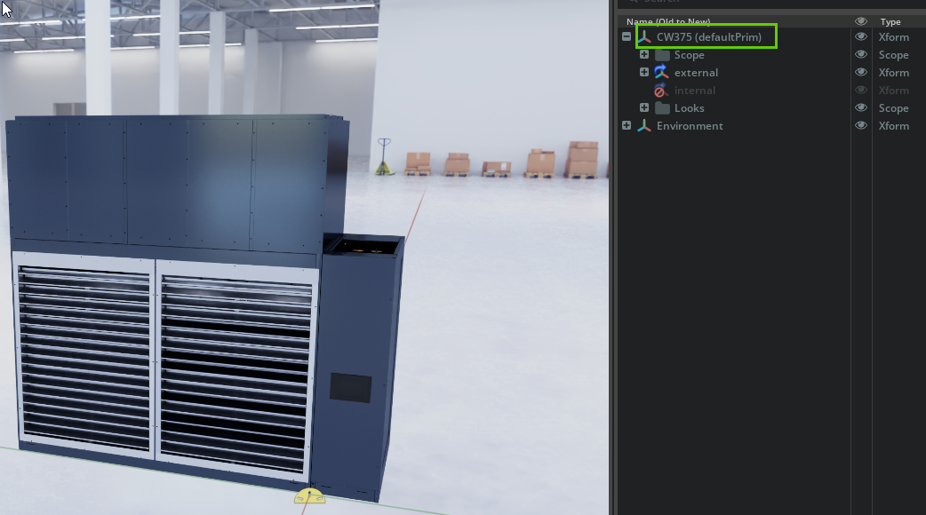
Open your main geometry file in USD Composer. Note the defaultPrim name (you will need it later).
Reset to a new, empty scene (no environment or lighting). Ensure your default environment is Z-Up and set to meters.
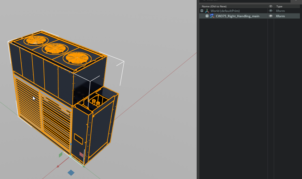
Drag and drop the main geometry file into the new stage. This creates a payload reference (indicated by the blue arrow next to the XForm node).
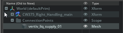
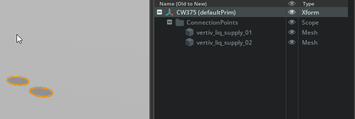
Right-click in the Stage window > Create > Scope named
ConnectionPoints.Identify the connection points for thermal cooling, electrical connectivity, and airflow vents:
Use Create > Mesh > Plane (rectangular) or Disk (circular) to generate connection point geometry prims
Drag the new prim into the
ConnectionPointsscope if created outside the hierarchy
Position and orient each prim to its corresponding opening on the main asset
Name per the convention table above
Delete the payload reference to the main asset. You should be left with only the
ConnectionPointsscope and the prims you created.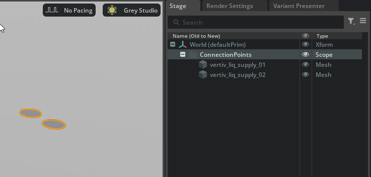
Select all connection point geometry prims and in the Properties panel, change their Purpose from
defaulttoguide.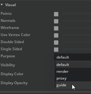
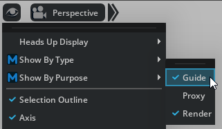
If they disappear in the viewport, go to the Eye icon in the 3D View and choose Show By Purpose > Guide.
Rename the defaultPrim to match the name from your original main geometry file. Double-click on the defaultPrim in the Stage panel and rename it.
Save the file as
<AssetName>_ConnectionPoints.usd(for example,CW375_ConnectionPoints.usd).Reload the main geometry file. In the Layers panel, drag and drop the connection points file as a sublayer.
Result#
The connection points geometry prims should precisely line up with the main geometry, and the USD stage should show the full set of composition arcs.
See also
CAD to USD - Where connection points fit in the pipeline
Metadata - Apply metadata alongside connection points
Terminology for Simulation Assets - SimReady terminology