

Joint Parameter Tuning Example: Robotiq 2F-85#
A worked example of tuning articulation joint drives (spring/damper model) for a robotic gripper, the Robotiq 2F-85. It applies the concepts from the Articulation Stability guide to a concrete asset. The estimates here are deliberately crude — they establish a value range, not precise numbers. Gravity is taken as 10 m/s^2 throughout.
Units. PhysX uses radians for angular quantities; USD uses degrees. For angular stiffness/damping, one USD unit equals
180/piPhysX units. This example uses PhysX units unless stated otherwise; map accordingly when authoring USD.
Test Scenes#
Tune with minimal scenes: the gripper plus one object to grasp. Start with the object’s gravity disabled, close the gripper, and watch for instability or penetration; then enable gravity and check the grip holds; then apply a lifting force. Cover several cases:
Primitive objects (box/cylinder) at different thicknesses so the gripper grips at different opening angles.
A collision-challenging thin-walled shape (cup, bowl).
The geometrically hardest object your application requires.
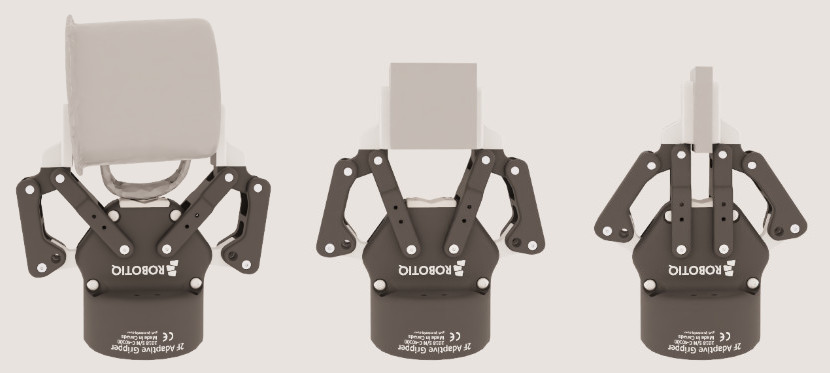
Figure: The same gripper across three object shapes. Left holds a thin-walled cup, the collision-challenging case. Center holds a box, the primitive case. Right holds a thin plate. Each object thickness closes the fingers to a different opening angle, which is why one tuning pass has to cover all three.
The Gripper#
Six revolute joints model the gripper’s degrees of freedom. Only joint J0 has a drive; the other five are mimic joints of J0 (gearing 1 or -1, offset 0), driven indirectly. J0 ranges 0 deg (fully open) to 47 deg (fully closed).
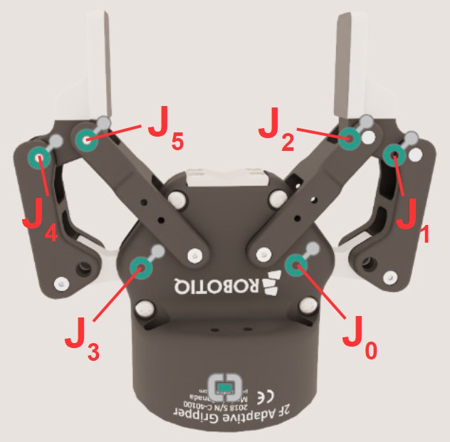
Figure: Joint numbering on the two fingers. The joints come in mirrored triples. On one finger, J0 sits at the palm, J1 on the outer link, and J2 at the fingertip; the other finger carries J3, J4, and J5 in the same positions. J0 is the only driven joint, so every force figure below is derived at J0 and the remaining five follow it as mimic joints.
Maximum Drive Force and Joint Velocity#
Set limits first so the simulation stays in the range expected of the real gripper (from the mechanical specification, or from experiments).
Maximum drive force#
The gripper holds a 5 kg box at friction coefficient 0.3, requiring about
[ \frac{mass \cdot gravity}{0.3} = \frac{5 \cdot 10}{0.3} \approx 166\ \text{N} ]
so 83 N per finger. Torque at the joint from the ~0.04 m lever arm:
[ \tau = F \cdot r = 83 \cdot 0.04 \approx 3.3\ \text{Nm} ]
Round up to 4 Nm per joint. Since J0 drives all six joints (itself plus five mimic joints, gearing 1), set J0’s max drive force to
[ J_0\ maxDriveForce = 6 \cdot 4 = 24\ \text{Nm} ]
Maximum joint velocity#
Max finger speed is 0.15 m/s; each finger travels 0.0425 m to close, so
[ t = \frac{0.0425}{0.15} \approx 0.28\ \text{s} ]
Over J0’s 47 deg range:
[ J_0\ maxJointVelocity = \frac{47}{0.28} \approx 168\ \text{deg/s} ]
Generally do not set max joint velocity on the mimic joints (leave them at default). With non-compliant mimic joints, a too-low limit can cause instability; the mimic joints already follow J0’s velocity by design.
Drive Stiffness and Damping#
A spring/damper drive produces F = s*dx - d*dv (stiffness s, damping d,
position error dx, velocity error dv). Check the choice against natural
frequency and damping ratio (angular joint, inertia i):
[ nf = \sqrt{s / i} \qquad dr = \frac{d}{2\sqrt{s \cdot i}} ]
Use the most conservative joint — the one on the lightest link. For J0, the lighter link’s inertia about the rotation axis (through the parallel-axis theorem with mass 0.0127 kg, offset 0.01 m) is about
[ 2.1\text{e-}6 + 0.0127 \cdot (0.01)^2 \approx 3.4\text{e-}6\ \text{kg m}^2 ]
The asset’s original stiffness of ~5700 gives nf ~ 4.0e4 rad/s, far above the
250 Hz simulation frequency (even counting 64 TGS position iterations as full
steps, ~1.6e4). Such a mismatch is unstable.
Instead of matching nf to the sim frequency, derive stiffness from the required
force at the smallest target delta. If max drive force should be reached by a 5
deg (~0.087 rad) delta at J0:
[ s = \frac{maxDriveForce}{0.087} = \frac{24}{0.087} \approx 275\ \text{kg m}^2/\text{s}^2 ]
which gives nf ~ 9.0e3 rad/s — still large, but far better than 5700’s value,
and worth testing. Then derive damping from a damping ratio (1.0 = critical, a
good starting point):
[ d = dr \cdot 2\sqrt{s \cdot i} = 1.0 \cdot 2\sqrt{275 \cdot 3.4\text{e-}6} \approx 0.06\ \text{kg m}^2/\text{s} ]
Implicit spring caveat#
PhysX uses an implicit spring formulation, which prevents explosive forces from a too-large timestep but behaves unintuitively far from the natural frequency: past a point, increasing stiffness reduces the applied force, and increasing damping applies almost no damping. Ignoring damping, the force is roughly
[ F = \frac{s \cdot dx}{dt^2 \cdot nf^2 + 1} ]
so the force matches the explicit spring only when dt^2 * nf^2 is small — again,
keep the natural frequency near the simulation frequency.
Armature#
Armature assigns inertia (or mass, for linear DOFs) to a joint — modeling a motor
rotor and gearbox — and lowers the drive’s natural frequency (raising effective
inertia). For example, an armature of 5.0e-3 kg m^2 on J0 drops nf from ~9.0e3
to about
[ \sqrt{275 / 5.0\text{e-}3} \approx 234\ \text{rad/s} ]
which could work even at 60 Hz (with 64 TGS position iterations). Derive it from
a motor datasheet as reflected inertia armature = i_m * G^2 (rotor inertia
i_m, gear ratio G). Large relative armature changes the physical model, so
verify the motor spec and gear ratio justify it.
Mimic Joint Compliance#
Mimic joints can be hard constraints (large corrective forces) or compliant (spring/damper that allows some divergence). Start with non-compliant mimic joints and add compliance only when competing hard constraints cannot be resolved without yielding; sometimes increasing armature avoids the need. Compliance is set through natural frequency and damping ratio, not stiffness and damping — do not copy drive stiffness/damping into the compliance parameters.
Verification and Fine-Tuning#
On the minimal scenes, verify that: the simulated open-to-close time roughly matches the spec; the gripper holds the maximum rated load under gravity across finger states; there is no significant penetration (check collision meshes, not just visuals — use OmniPVD); and there is no significant jitter. Then fine-tune: can stiffness or max drive force be lowered while still holding the load? Recompute related parameters when you change one (re-derive damping when you change stiffness). If instability persists despite spec-based values, increase position iterations, reduce the timestep, or add/increase armature. Get the gripper right on minimal scenes before simulating a full robot.
Further reading: