

USD Attributes#
Apply OmniSensorGenericAcousticWpmAPI to an OmniAcoustic prim.
The defaults create one transducer at the prim’s origin that transmits and
receives once per cycle. All model attributes belong on that prim.
A mount locates a transducer. A firing event sends a pulse from one mount to a group of receivers. Each receiver records a sampled echo envelope on a channel id; this is a signal way. Mounts, receiver groups and firing sequences define the array and its output shape.
The default operating mode is basic; omni:sensor:WpmAcoustic:enableInterference
selects interference mode. The sections below explain which mode reads each
attribute. See Sensor API Schemas for declarations
and defaults, Set Up an Acoustic Sensor to request SignalWays, and
Outputs to read it.
Attributes use the shared omni:sensor:* namespace, the model-specific
omni:sensor:WpmAcoustic:* namespace, or an instance namespace for a mount,
receiver group or firing sequence. See namespace conventions and
topology attributes.
Identification#
OmniSensorGenericAcousticWpmAPI defaults omni:sensor:modelName to
"AcousticWPM", omni:sensor:modelVendor to "NVIDIA",
omni:sensor:marketName to "Generic" and omni:sensor:frameRate
to (30, 1). It retains the base-schema defaults for
omni:sensor:startTime ((0, 1)) and omni:sensor:frameLimit (0).
The three names are labels; frameRate schedules the sensor. See
Sensor Configuration for shared
attributes and Sensor Scheduling for
stepping and delivery.
Ray tracing, frame and firing direction#
Both operating modes use the following controls to sample the space around each transmitting mount. They affect propagation, not output layout.
omni:sensor:WpmAcoustic:azSpanDegandomni:sensor:WpmAcoustic:elSpanDegare the full angular span, in degrees, of the lobe traced around each mount’s axis, in azimuth and in elevation. Both default to 90.omni:sensor:WpmAcoustic:raysPerDegis the ray density per degree along each axis, default 3. A lobe therefore carriesazSpanDeg * raysPerDegbyelSpanDeg * raysPerDegrays, and every firing event traces one lobe from its transmitting mount (the events are described under Mounts, receiver groups and firing sequences).omni:sensor:WpmAcoustic:traceTreeDepthis the maximum number of surfaces a pulse’s path may bounce off before the model stops following it, default 2. More depth lets more indirect paths reach a receiver: more echoes in the envelope, including ghost echoes from paths that bounced more than once, at more tracing cost. A depth of 1 keeps single-bounce echoes only: the pulse reaches a surface and returns to a receiver from there.
Warning
Tracing cost grows with the ray count. Doubling raysPerDeg quadruples
the rays of every lobe, and a wide span at a high density, multiplied by
several events per cycle and a deeper trace tree, is what makes an acoustic
frame slow. Raise the density for stable coverage of the surfaces that
matter, and raise the depth only for a scenario that needs indirect paths.
The tracing lobe is centered on the prim’s local -Z axis; see
sensor orientation.
Set Up an Acoustic Sensor shows the example’s orientation transform.
Mount transforms use the sensor frame:
position:[x, y, z]in meters.rotation:[roll, pitch, yaw]in degrees.
The sensor-frame axes are:
+X: firing direction (prim -Z).
+Y: left (prim -X).
+Z: up (prim +Y).
Zero rotation aligns the mount with the firing direction. Roll rotates about that direction, pitch tilts vertically, and yaw turns horizontally. Mounts move with the sensor prim. See mount attributes.
Trace depth is the only configurable propagation limit. Other propagation limits are fixed; see Limitations.
Physical sensor#
The following attributes use the omni:sensor:WpmAcoustic: prefix:
membraneDiameter: receiving-membrane diameter in meters (default0.03). Larger membrane area increases received amplitude. Both operating modes use this attribute.centerFrequency: transmitted pulse frequency in Hz (default51200). EachSignalWaysoutput reports it ascenterFrequencyHz.bandwidth: transmitted pulse bandwidth in Hz (default3000).pulseDuration: transmitted pulse duration in seconds (default0.0025).pulsePower: dimensionless transmitted-pulse power (default513.57). It scales echo amplitudes in basic mode and is ignored in interference mode.sampleDuration: time between echo-envelope samples in basic mode, in seconds (default0.0001024, or 102.4 µs). It determines the range-bin spacing and is ignored in interference mode. The output reports it in microseconds assampleDurationUs; see Outputs for converting sample indices to ranges.
Close range#
Basic mode boosts early echoes at the start of each envelope. Configure the
boost with these attributes under omni:sensor:WpmAcoustic::
closeRange: the threshold up to which the boost applies. A value of0or less disables it.closeRangeDecay: the point beyond which the boost fades.closeDirectAmplandcloseDirectAmplBase: boost settings for echoes received by the transmitting mount.closeIndirectAmplandcloseIndirectAmplBase: boost settings for echoes received by another mount.
Interference mode uses a fixed boost and ignores these attributes.
The "AM" signal mode applies a stronger boost than "CHIRP"; refer to
Signal processing.
Note
The defaults of the six are calibration constants, declared with many digits in the schema. Author them exactly as declared or leave them unauthored; a rounded copy is not the same calibration.
Noise#
Basic mode adds uniformly distributed noise to each envelope sample after
amplification. omni:sensor:WpmAcoustic:noiseMin and
omni:sensor:WpmAcoustic:noiseMax set the lower and upper limits
(defaults 0.3 and 1.7). Both are dimensionless, like envelope amplitudes.
Noise is sampled again for each frame, so envelopes vary even when the scene is unchanged. Interference mode adds no noise.
Basic-mode noise can produce nonzero samples without an echo. Use the validity flag to identify responses.
Signal processing#
omni:sensor:WpmAcoustic:signalMode controls amplitude shaping in both
operating modes:
CHIRP(default): no additional amplitude boost.AM: stronger close-range boost and increased echo amplitudes at ranges from 3 m to 4.5 m, relative toCHIRP.
Values are case-insensitive. Any other value rejects the entire parameter update; see Sensor Definition Validation.
omni:sensor:WpmAcoustic:enableInterference selects the
operating mode.
Basic mode also uses two coefficient arrays under omni:sensor:WpmAcoustic::
gainCoeffs: evaluates a polynomial of the sample’s one-way range in meters. The result multiplies the sample amplitude.directivityCoeffs: evaluates a polynomial of the angle from the mount’s axis in radians. The result scales both transmission strength and receive sensitivity in that direction.
Both arrays list coefficients in ascending power order: element 0 is the
constant term, and element i multiplies the input raised to power i.
Each defaults to seven coefficients; see Sensor API Schemas for their values.
Basic mode requires both arrays to be non-empty. Supply complete coefficient lists or retain the defaults. Interference mode ignores both arrays.
Operating modes#
omni:sensor:WpmAcoustic:enableInterference selects the operating mode:
false(default): basic mode simulates concurrent transmissions without interference between them.true: interference mode also simulates interference between concurrent transmissions from multiple mounts, at a higher computational cost.
You can change the mode while the sensor runs.
Both modes use:
Mounts, receiver groups and firing sequences.
azSpanDeg,elSpanDegandraysPerDegfor ray sampling.traceTreeDepthfor tracing depth.membraneDiameterandsignalModefor amplitude processing.
Only basic mode uses:
pulsePowerandsampleDuration.gainCoeffsanddirectivityCoeffs.The six close-range attributes.
noiseMinandnoiseMax.
Interference mode uses fixed pulse power, gain, directivity and close-range boost, with no added noise.
Mounts, receiver groups and firing sequences#
Apply mount, receiver-group and firing-sequence schema instances to the same
OmniAcoustic prim. Add an instance for each additional mount, group or
sequence.
Piece |
Schema |
Instances |
Attributes |
|---|---|---|---|
Sensor mount |
|
|
Where one transducer sits: |
Receiver group |
|
|
Which mounts listen together: |
Firing sequence |
|
|
One repeating cycle of firing events, as four arrays with one entry per
event: |
Attribute names follow the instance:
omni:sensor:WpmAcoustic:sensorMount:<instance>:<attribute>,
omni:sensor:WpmAcoustic:rxGroup:<instance>:<attribute> and
omni:sensor:WpmAcoustic:firingSeq:<instance>:<attribute>.
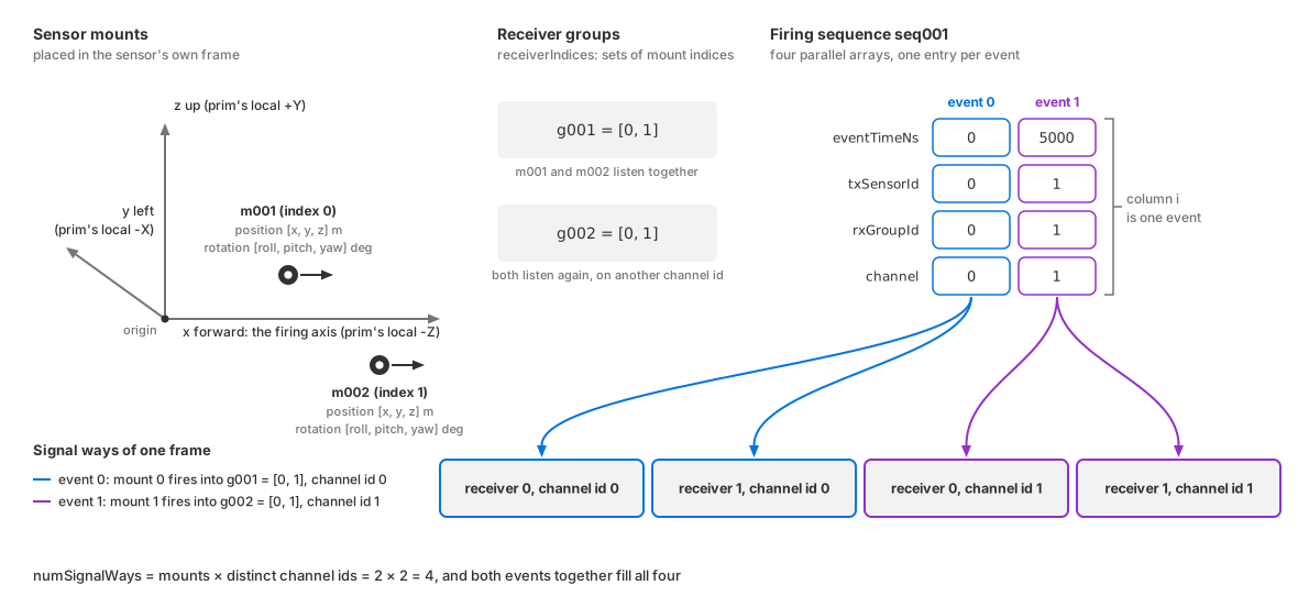
How the three pieces fit: mounts m001 and m002 sit in the sensor
frame with a position and a rotation each; receiver groups g001 and
g002 are sets of mount indices; a firing sequence is four parallel
arrays with one entry per event; and one event, from the mount its
txSensorId names into the group its rxGroupId names, writes one
signal way per receiver of that group, filed under the event’s channel id.#
OmniSensorGenericAcousticWpmAPI applies three default schema instances:
OmniSensorWpmAcousticSensorMountAPI:m001: a mount at the origin with no rotation.OmniSensorWpmAcousticRxGroupAPI:g001: a receiver group containing mount0.OmniSensorWpmAcousticFiringSeqAPI:seq001: one firing event at time0, from mount0to group0on channel0.
Together, these define one transducer that transmits and receives once per cycle, producing one signal way.
Override the default instances’ attributes directly. To add a mount, group
or sequence, apply another schema instance, such as
OmniSensorWpmAcousticSensorMountAPI:m002, and author its attributes.
The example scene’s sensor prim shows the default topology in use: it applies the main schema, sets the frame rate and the four ray-tracing attributes, and authors no mount, group or sequence of its own.
#usda 1.0
    # The sensor fires along its local -Z. This transform maps that onto world
    # +X, where the wall stands, and puts the sensor 0.5 m up, level with the
    # wall's center. It is authored as a matrix rather than as translate/rotate
    # ops so it matches the layout the runtime "omni:xform" attribute expects.
    def OmniAcoustic "Acoustic" (
        prepend apiSchemas = ["OmniSensorGenericAcousticWpmAPI"]
    )
    {
        double2 omni:sensor:frameRate = (10, 1)

        # Ray tracing: a wide ultrasonic lobe pointing along sensor -Z.
        float omni:sensor:WpmAcoustic:azSpanDeg = 90
        float omni:sensor:WpmAcoustic:elSpanDeg = 60
        uint omni:sensor:WpmAcoustic:raysPerDeg = 3
        uint omni:sensor:WpmAcoustic:traceTreeDepth = 2

        matrix4d xformOp:transform = ( (0, -1, 0, 0), (0, 0, 1, 0), (-1, 0, 0, 0), (0, 0, 0.5, 1) )
        uniform token[] xformOpOrder = ["xformOp:transform"]
    }
from pxr import Gf, Sdf

world = stage.DefinePrim("/World", "Xform")

acoustic = stage.DefinePrim("/World/Acoustic", "OmniAcoustic")
acoustic.AddAppliedSchema("OmniSensorGenericAcousticWpmAPI")
acoustic.CreateAttribute("omni:sensor:frameRate", Sdf.ValueTypeNames.Double2, custom=False).Set(
    Gf.Vec2d(10.0, 1.0)
)
acoustic.CreateAttribute(
    "omni:sensor:WpmAcoustic:azSpanDeg", Sdf.ValueTypeNames.Float, custom=False
).Set(90.0)
acoustic.CreateAttribute(
    "omni:sensor:WpmAcoustic:elSpanDeg", Sdf.ValueTypeNames.Float, custom=False
).Set(60.0)
acoustic.CreateAttribute(
    "omni:sensor:WpmAcoustic:raysPerDeg", Sdf.ValueTypeNames.UInt, custom=False
).Set(3)
acoustic.CreateAttribute(
    "omni:sensor:WpmAcoustic:traceTreeDepth", Sdf.ValueTypeNames.UInt, custom=False
).Set(2)
# Map sensor-local -Z to world +X and place the sensor 0.5 m above ground.
acoustic.CreateAttribute("xformOp:transform", Sdf.ValueTypeNames.Matrix4d, custom=False).Set(
    Gf.Matrix4d(
        (0.0, -1.0, 0.0, 0.0), (0.0, 0.0, 1.0, 0.0), (-1.0, 0.0, 0.0, 0.0), (0.0, 0.0, 0.5, 1.0)
    )
)
acoustic.CreateAttribute(
    "xformOpOrder",
    Sdf.ValueTypeNames.TokenArray,
    custom=False,
    variability=Sdf.VariabilityUniform,
).Set(["xformOp:transform"])
Lay Out a Transducer Array grows this prim into a two-mount array step by step.
Mounts, receiver groups and firing sequences are ordered lexicographically by
instance name, ignoring case. receiverIndices, txSensorId and
rxGroupId index those orderings. Use zero-padded names such as m001
and m010; unpadded m10 sorts before m2. Names differing only in
case identify the same instance. The sensor cycles through firing sequences
in this order, reported by cycleIndex.
A firing sequence is four parallel arrays, one entry per event. Element
i of eventTimeNs, txSensorId, rxGroupId and channel describes
the same event: when it happens, which mount transmits, which group listens,
and which output channel the result is filed under. Author all four together,
with the same length.
Each event transmits from one mount to all mounts in the receiver group
selected by rxGroupId. Define separate groups for the receiver subsets
your events require.
Number channel ids consecutively from 0. Use a separate id for each event
whose echoes must remain distinguishable. Each receiving-mount/channel-id
pair has one signal way; see output layout.
Indices and channel ids range from 0 to 255. Each of these must be
at most 255:
The number of mounts.
The number of distinct channels.
The mount count multiplied by the distinct channel count (the number of signal ways).
Validation does not enforce these capacity limits.
Topology references must satisfy these rules:
Receiver indices and
txSensorIdmust refer to existing mounts.rxGroupIdmust refer to an existing receiver group.Each receiver group must contain at least one receiver index.
The sensor removes nonexistent mount indices from receiver groups and
replaces nonexistent rxGroupId values with group 0. It logs both
kinds of correction as errors and continues running with the modified topology.
Validation checks scalar and coefficient attribute types and the value of
signalMode. It does not check physical plausibility: implausible values
can be accepted and affect the output. See
Sensor Definition Validation for the
validation process.
Runtime updates#
Runtime updates support ray-tracing, physical, close-range, noise and
signal-processing attributes; mount transforms; receiver groups; firing
sequences; and enableInterference. The sensor need not be recreated.
signalMode uses the same update mechanism.
Accepted edits may reallocate resources and take longer to apply, including changes to scalar attributes such as
noiseMax,pulsePower,sampleDurationandsignalMode. Interference mode does not readgainCoeffsordirectivityCoeffs; edits to these take effect when basic mode is next selected.A frame already in flight finishes on the configuration it started with. The sensor itself is not recreated, so its
frameIdcarries on counting across the change.Runtime Parameter Updates states the outcomes an edit can have and what a rejected update costs.
See Retune the Sensor While It Runs for checking updates through echoed parameters, output dimensions and validity flags.