

Parameterize a Solid-State Lidar: Blickfeld Cube 1#
The Blickfeld Cube 1 uses two resonant mirrors to steer a Lissajous scan
pattern. This tutorial calculates pulse directions and times from the
manufacturer’s mirror equations, using three public documents and one
selected operating point. It produces 5,850 emitter entries on an
OmniLidar prim.
The published material conflicts in four places — the frame duration, the ramp split, the mirror phase and the direction of the first line’s vertical motion. The profile follows the equations in the first three and the described scan direction in the last, with the choices and their consequences explained below.
No captured Cube 1 frame is available for this example. The profile
Blickfeld_Cube1_Analytic.usda
and its generator
generate_blickfeld_cube1_profile.py
therefore implement an analytic pattern derived from the software manual.
They do not represent a captured factory preset or a certified device model.
Unpublished optical power, receiver response, thresholds, noise, corrections
and intensity transfer remain generic or approximate and require calibration
against measured data.
Source documents#
This recipe uses three Blickfeld sources:
Cube 1 Datasheet v2.1, document v2.1-EN-#42369-IH, published in 2022 for firmware v1.25.10.
Blickfeld scan-pattern documentation, from the Blickfeld Software Manual v1.6.20, accessed July 27, 2026.
Blickfeld protocol definitions, Blickfeld-Scanner-Library v2.20.6, accessed July 27, 2026.
The datasheet defines the Cube 1 product envelope. The scan-pattern page supplies the mirror equations, the definition of a scanline, the relationship between frame duration and line count, the exemplary ramp, and the observed line order. The protocol definitions distinguish configurable pulse modes and describe the fields available in a captured point-cloud frame.
The revisions are not one matched source set: the 2022 datasheet targets firmware v1.25.10, while the current software manual and protocol documentation are newer. Recheck the constraints reported by the target device before copying this profile into a production configuration.
Source confidence#
Each mapping below belongs to one of four categories, sometimes qualified; a value this profile picks from inside a published range is marked Selected instead:
Category |
Meaning |
How to use it |
|---|---|---|
Direct |
Source and simulation values have the same physical meaning and units. |
Copy the value, then verify coordinate, boundary, and array conventions. |
Derived |
The source provides enough information to calculate the value. |
Preserve the equation and every selected source assumption. |
Approximation |
A published claim exists, but the generic core uses different semantics. |
Use it as an initial condition and validate it against measurements. |
Calibration |
Public sources do not define the value or the exact device behavior. |
Retain a documented generic starting value and replace it with measured data. |
Read the product-level specifications#
The datasheet’s optical performance block gives the product envelope this profile is built inside: a maximum 70 x 30 degree field of view, 5 to 400 scanlines per frame, 0.4 to 1.0 degree horizontal resolution, a 1.5 to 75 m typical application range, a 250 m detection range, more than 30 m on a 10% target under stated conditions, range resolution below 1 cm, and bias-free RMS precision below 2 cm at 10 m on a 50% target.
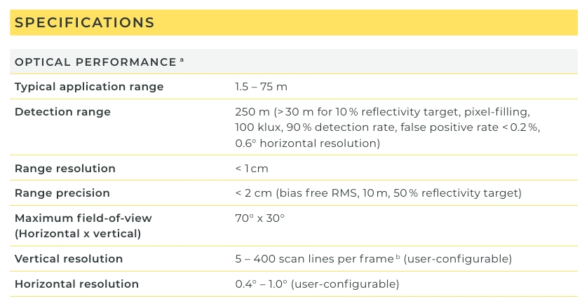
Excerpt from the Cube 1 Datasheet v2.1, page 1.#
A second block covers scan cadence, laser, returns and output fields: a 1.5 to 50 Hz frame rate, more than 500 scanlines per second, a 905 nm wavelength, 0.4 degree beam divergence with square 7 cm and 35 cm spot examples at 10 m and 50 m, up to three returns with only one below 5 m, and per-point distance, intensity, Cartesian position, angles and a nanosecond timestamp.
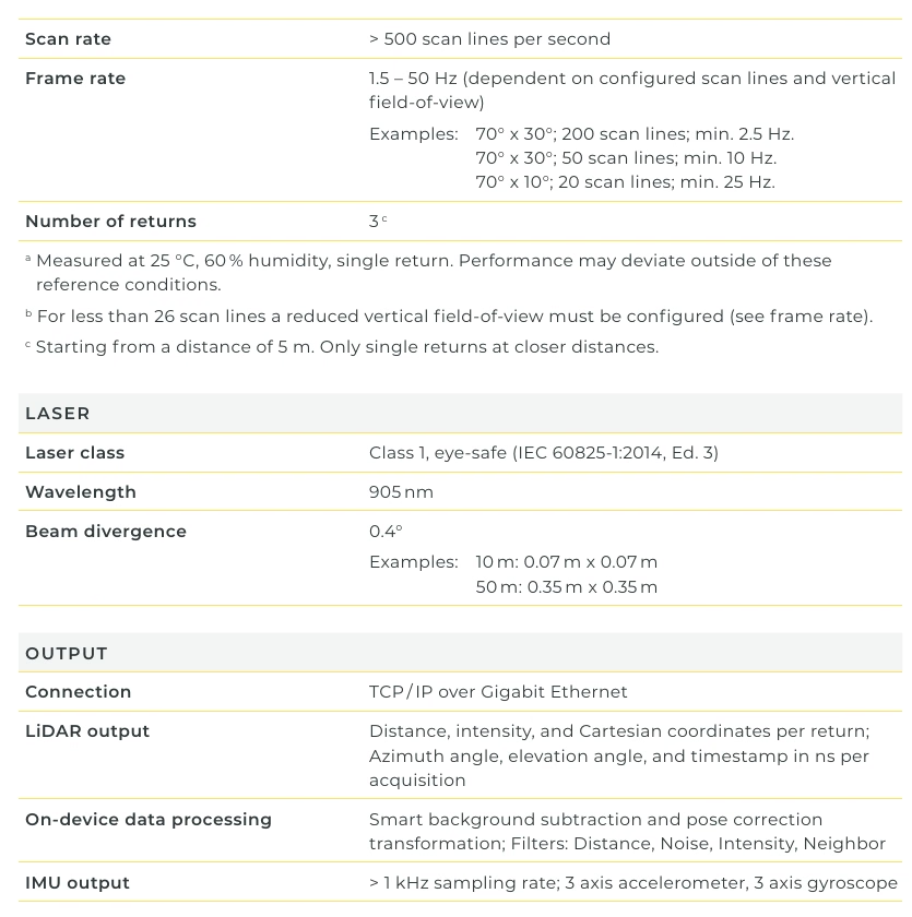
Excerpt from the Cube 1 Datasheet v2.1, page 1.#
The source-to-model mapping used by this example is:
Manufacturer information |
Simulation attribute or action |
Value in this profile |
Category |
Notes |
|---|---|---|---|---|
Two resonant MEMS mirrors and software-defined pattern |
|
|
Direct mechanism, derived schedule |
Every virtual emitter is one analytically derived pulse opportunity. |
Maximum 70 x 30 degree field of view |
Analytic mirror envelope |
70 x 30 degrees nominal |
Direct envelope |
The discrete pulse grid does not fire exactly at the turning points. |
5-400 scanlines per frame |
|
|
Direct datasheet example |
The datasheet pairs 50 lines with a 70 x 30 degree field of view and a minimum 10 Hz frame rate. |
0.4-1.0 degree horizontal resolution |
Explicit horizontal grid |
0.6 degrees |
Selected within range |
This is also the resolution in the datasheet’s conditional 10% target claim. |
More than 500 scanlines per second |
Analytic mirror frequency |
250 Hz, giving a nominal 500 lines/s |
Derived approximation |
This follows the rounded 50-line, 10 Hz datasheet example; it is not a measured eigenfrequency. |
1.5-50 Hz frame rate |
|
|
Selected lower bound |
The datasheet publishes a minimum 10 Hz for its 50-line, 70 x 30 degree example; this profile selects exactly 10 Hz. |
Typical application range 1.5-75 m |
|
1.5 m near limit; validate through 75 m |
Approximation |
The source does not call 1.5 m a hard minimum. |
Detection range 250 m |
|
250 m |
Approximation |
Target reflectivity and other conditions are not stated for the 250 m limit. |
More than 30 m on a 10% target under stated conditions |
|
0.10, 30 m |
Approximation |
This is a conservative generic threshold anchor, not a reproduction of detection probability. |
Range resolution below 1 cm |
|
0.01 m |
Conservative approximation |
The published bound does not provide an exact reporting increment. |
Bias-free RMS precision below 2 cm at 10 m and 50% reflectivity |
|
0.02 m |
Approximation |
The generic error grows with range and does not encode the source conditions. |
905 nm wavelength |
|
905 nm |
Direct |
Used by the material and radiometric model. |
0.4 degree beam divergence |
|
0.4, 0.4 degrees |
Direct |
The square 7 cm and 35 cm spot examples at 10 m and 50 m support both axes. |
Up to three returns, one below 5 m |
|
3 |
Partly direct |
The generic global capacity cannot reduce the limit to one below 5 m. |
Distance, intensity, Cartesian position, angles, and nanosecond timestamp |
|
Requested as needed |
Direct output concepts |
Blickfeld’s exact encoding, selection, and intensity transfer remain separate. |
The attributes named in that table are authored on the sensor prim under
omni:sensor:Core:; what each of them means in general is on
Configure a Firing Pattern, Tune Intensity and Point Drops and
USD Attributes. The channels the last row refers to are in
Outputs.
Select an analytic reference pattern#
Cube 1 does not have one immutable firing pattern. The device exposes horizontal and vertical field of view, up-ramp and down-ramp line counts, pulse mode, and related constraints. An exact profile normally starts with one recorded point-cloud frame and the active scan-pattern configuration.
This profile selects the following operating point within the published limits:
Choice |
Value |
Reason |
|---|---|---|
Nominal field-of-view envelope |
70 x 30 degrees |
Maximum Cube 1 envelope from the datasheet. |
Mirror frequency |
250 Hz |
Derived from 50 lines, 10 Hz, and the published line-count equation. |
Scanlines |
50 |
Matches the datasheet’s 70 x 30 degree, minimum 10 Hz example. |
Ramp |
Continuous 3:1 duration ratio |
Follows the published exemplary function; its peak occurs 37.5 scanlines into this frame. |
Horizontal spacing |
0.6 degrees |
Within the configurable range and used by one datasheet detection claim. |
Pulse-grid behavior |
Same grid on every line |
Corresponds to |
Capture mode |
Whole scans, |
Delivers one explicit solid-state frame per 100 ms scan, completed at the period boundary. |
This is not claimed to be a named vendor preset. In particular, the protocol
documents INTERLEAVE as the default pulse type and describes a quarter-spacing
shift between alternating scanlines. It does not define the sign of that shift, the
initial grid phase, or the edge-rounding rule. The profile therefore uses the
simpler documented equal-horizontal-angle behavior and leaves interleaving for
validation against a captured frame.
Build the profile#
Start with an OmniLidar prim and apply the generic core API:
#usda 1.0

def OmniLidar "Blickfeld_Cube1_Analytic" (
    prepend apiSchemas = ["OmniSensorGenericLidarCoreAPI"]
)
{
    string omni:sensor:modelName = "LidarCore"
    string omni:sensor:modelVersion = "0"
    string omni:sensor:modelVendor = "NVIDIA"
    string omni:sensor:marketName = "Blickfeld Cube 1"
    double2 omni:sensor:frameRate = (10, 1)

    token omni:sensor:Core:scanType = "SOLID_STATE"
    bool omni:sensor:Core:partialOutputs = false
}
from pxr import Gf, Sdf

lidar = stage.DefinePrim("/Blickfeld_Cube1_Analytic", "OmniLidar")
lidar.AddAppliedSchema("OmniSensorGenericLidarCoreAPI")
lidar.CreateAttribute("omni:sensor:modelName", Sdf.ValueTypeNames.String, custom=False).Set(
    "LidarCore"
)
lidar.CreateAttribute("omni:sensor:modelVersion", Sdf.ValueTypeNames.String, custom=False).Set(
    "0"
)
lidar.CreateAttribute("omni:sensor:modelVendor", Sdf.ValueTypeNames.String, custom=False).Set(
    "NVIDIA"
)
lidar.CreateAttribute("omni:sensor:marketName", Sdf.ValueTypeNames.String, custom=False).Set(
    "Blickfeld Cube 1"
)
lidar.CreateAttribute("omni:sensor:frameRate", Sdf.ValueTypeNames.Double2, custom=False).Set(
    Gf.Vec2d(10.0, 1.0)
)
lidar.CreateAttribute("omni:sensor:Core:scanType", Sdf.ValueTypeNames.Token, custom=False).Set(
    "SOLID_STATE"
)
lidar.CreateAttribute(
    "omni:sensor:Core:partialOutputs", Sdf.ValueTypeNames.Bool, custom=False
).Set(False)
omni:sensor:frameRate sets complete scans per second. Solid-state
scheduling does not use rotationDirection or rotPatternFiringResDeg.
See Lidar generic core model for the scan-type differences.
Derive frame duration and line rate#
Blickfeld defines one scanline as one half-period of the horizontal mirror. For mirror frequency \(f\), frame duration \(T\), and line count \(N\):
For the selected 50 lines and 10 Hz frame rate:
T = 1 / 10 Hz = 0.1 s
line_rate = 50 / 0.1 s = 500 lines/s
f = 50 / (2 * 0.1 s) = 250 Hz
This reproduces the rounded arithmetic of the datasheet’s 50-line, minimum 10 Hz
example. The separate >500 scanlines/s statement indicates that a real device
may run slightly faster; 250 Hz is a derived analytic value, not a measured Cube 1
eigenfrequency. The profile contains 5,850 candidate ray slots per frame and
therefore 58,500 candidate ray slots per second. That number is a result of this
analytic selection, not a published Cube 1 point-rate specification.
The scan-pattern page contains inconsistent example prose. It describes a frame as one mirror period, but also defines \(N=2Tf\) and calls 40 scanlines 20 periods. Its printed \(T=2/f\) for that example would produce four rather than 40 lines. This recipe follows the scanline definition and \(N=2Tf\). For its selected 50-line frame, that gives \(T=25/f\).
Use the published mirror functions#
The public page describes a 1:1 Lissajous pattern with horizontal and vertical functions:
where \(H\) and \(V\) are the nominal horizontal and vertical field-of-view envelopes. The exemplary ramp is:
The scan-pattern page plots the horizontal and vertical mirror movement over one frame, and the unequal ramp durations are visible in it: the vertical amplitude envelope rises over three quarters of the frame and falls over the remaining quarter, while the horizontal mirror runs at constant frequency throughout. The plotted values illustrate the mechanism and are not all Cube 1 profile values.
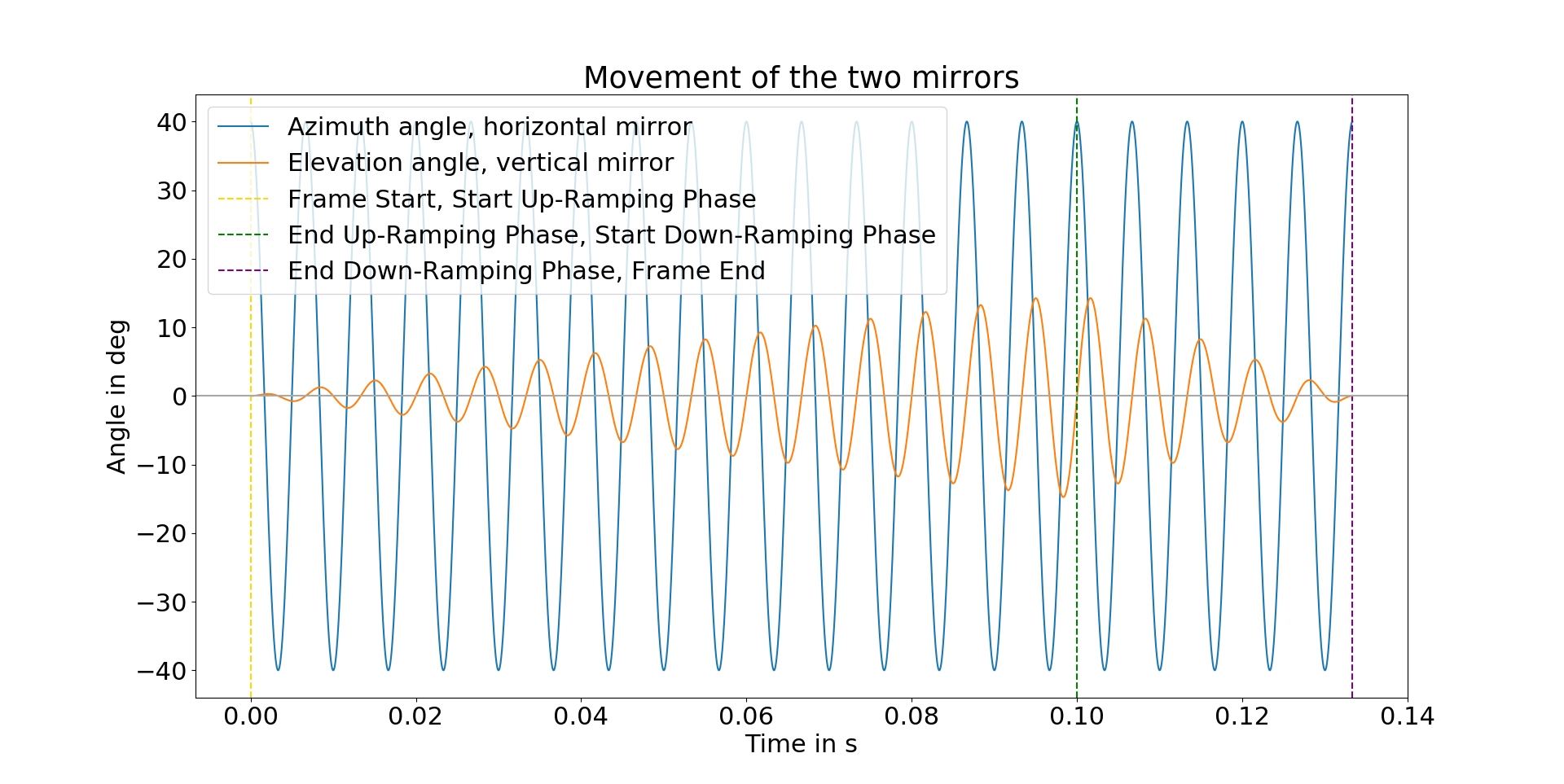
Figure 1 from the Blickfeld scan-pattern documentation.#
The ramp reaches one at three quarters of the frame. For 50 scanlines, that transition occurs 37.5 scanlines into the frame, halfway through scanline 37 when numbered from zero. The continuous analytic trajectory is well-defined, but it cannot be described as integer up-ramp and down-ramp line counts. The actual Cube 1 split for the datasheet example is not published. The prose on the same page calls these two halves; the formula and plot are unambiguously 3:1, so the profile follows the formula.
The page also states a \(\pi/4\) mirror phase difference, while the shown cosine and sine equations imply \(\pi/2\). The profile follows the explicit equations and the documented line order. An exact device fit must replace this analytic interpretation with captured directions and timestamps.
Sample horizontal angles#
A 0.6-degree grid cannot include both exact 70-degree endpoints symmetrically: 70 / 0.6 is not an integer. The profile centers 117 directions inside the envelope:
x[j] = -34.8 + 0.6 * j degrees, j = 0..116
This gives 116 exact 0.6-degree intervals, 69.6 degrees of sampled horizontal coverage, and a 0.2-degree margin to each mirror turnaround. Omitting the exact turning points also prevents adjacent scanlines from sharing one timestamp.
The mirror moves slowly near a turnaround and fastest at the center. Uniform
fireTimeNs increments would therefore contradict the published sinusoid. For
even line \(\ell=2k\), traverse \(x\) from +34.8 to -34.8:
For odd line \(\ell=2k+1\), traverse \(x\) from -34.8 to +34.8:
Calculate every value from absolute time and round once to nanoseconds. Do not accumulate already-rounded deltas. The resulting 5,850 times are strictly increasing:
Quantity |
Analytic result |
|---|---|
Rounded frame duration |
100,000,000 ns |
First pulse |
68,090 ns |
Last pulse |
99,931,910 ns |
Minimum adjacent pulse gap |
10,914 ns |
Gap across a mirror turnaround |
Approximately 136,180 ns |
List emitters in firing-time order. Equal times are permitted and fire as a
group; decreasing times fail validation. Invalid initial parameters
prevent initialization until corrected.
Invalid runtime updates are rejected in full, preserving previous values.
The renderer logs the error on omni.rtx and introspection also reports it.
See fire-time rules.
Derive vertical angles and coordinate signs#
The scan-pattern description says the first line starts near the center and moves from left to right while the vertical mirror moves toward the bottom. Later lines alternate direction and appear above, below, then farther above and below the first line. The page’s scanline-order plot shows exactly that fanning-out sequence, though it draws a ten-line, 80-degree horizontal illustration rather than this Cube 1 profile.
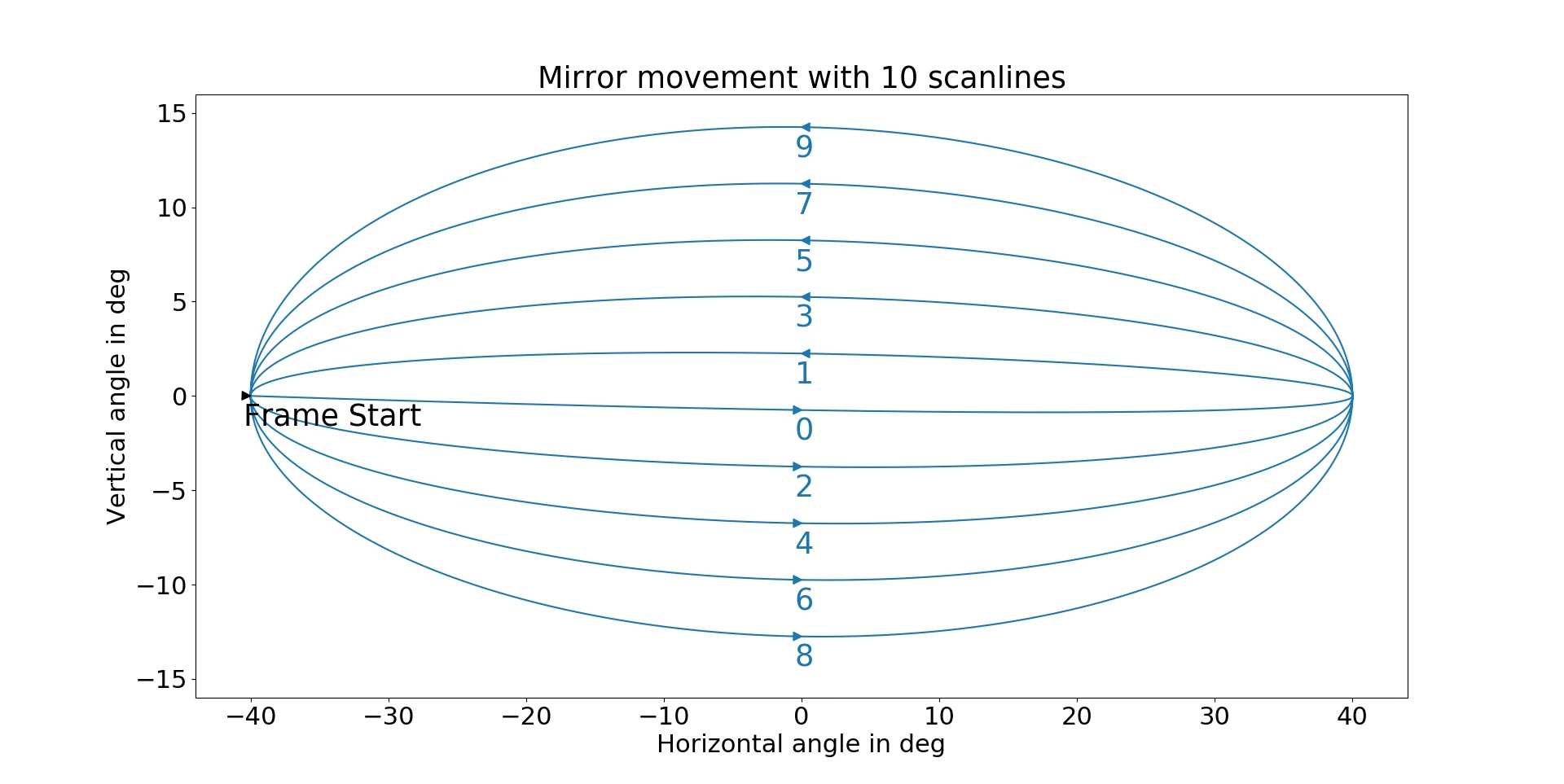
Figure 2 from the Blickfeld scan-pattern documentation.#
This recipe defines the core sensor frame as +X forward, +Y left, and +Z up. Positive physical azimuth is therefore toward sensor-left. For the first line, the analytic \(\theta_H\) moves from positive to negative, or left to right.
The solid-state core converts authored azimuth \(A\) to the physical direction \(-A\). The profile therefore authors:
azimuthDeg(t) = -theta_H(t)
elevationDeg(t) = -r(t) * 15 deg * sin(2*pi*250*t)
The vertical negation makes the first line move downward as described in the manual. It also resolves a sign conflict between the page’s equation, prose, and figure in one explicitly documented sensor frame. If recorded Blickfeld azimuth and elevation use a different sign convention, transform the captured directions once before replacing these arrays.
Although one pulse reaches the positive vertical extremum, the discrete pattern does not reach both nominal vertical limits. This profile’s authored elevations span approximately -14.600 to +15.000 degrees, or 29.600 degrees total. Do not report 70 x 30 degrees as the exact discrete point bounds.
Configure range and error#
The profile approximates the published range and precision limits with these settings:
#usda 1.0

def OmniLidar "Blickfeld_Cube1_Analytic"
{
    float omni:sensor:Core:nearRangeM = 1.5
    float omni:sensor:Core:farRangeM = 250.0
    float omni:sensor:Core:rangeResolutionM = 0.01
    float omni:sensor:Core:rangeAccuracyM = 0.02
    float omni:sensor:Core:minReflectance = 0.10
    float omni:sensor:Core:minReflectionRangeM = 30.0
    uint omni:sensor:Core:rangeCount = 1
    float[] omni:sensor:Core:rangesMinM = [1.5]
    float[] omni:sensor:Core:rangesMaxM = [250.0]
}
from pxr import Gf, Sdf

lidar = stage.DefinePrim("/Blickfeld_Cube1_Analytic", "OmniLidar")
lidar.CreateAttribute(
    "omni:sensor:Core:nearRangeM", Sdf.ValueTypeNames.Float, custom=False
).Set(1.5)
lidar.CreateAttribute("omni:sensor:Core:farRangeM", Sdf.ValueTypeNames.Float, custom=False).Set(
    250.0
)
lidar.CreateAttribute(
    "omni:sensor:Core:rangeResolutionM", Sdf.ValueTypeNames.Float, custom=False
).Set(0.01)
lidar.CreateAttribute(
    "omni:sensor:Core:rangeAccuracyM", Sdf.ValueTypeNames.Float, custom=False
).Set(0.02)
lidar.CreateAttribute(
    "omni:sensor:Core:minReflectance", Sdf.ValueTypeNames.Float, custom=False
).Set(0.1)
lidar.CreateAttribute(
    "omni:sensor:Core:minReflectionRangeM", Sdf.ValueTypeNames.Float, custom=False
).Set(30.0)
lidar.CreateAttribute("omni:sensor:Core:rangeCount", Sdf.ValueTypeNames.UInt, custom=False).Set(
    1
)
lidar.CreateAttribute(
    "omni:sensor:Core:rangesMinM", Sdf.ValueTypeNames.FloatArray, custom=False
).Set([1.5])
lidar.CreateAttribute(
    "omni:sensor:Core:rangesMaxM", Sdf.ValueTypeNames.FloatArray, custom=False
).Set([250.0])
These attributes make conditional product claims into the generic core’s required scalar parameters, so none is a perfect one-to-one mapping.
The lower end of the typical application range is used as an approximate near
limit, not asserted as the physical minimum range. The 250 m detection claim does
not state a target and is not the typical 75 m application limit. The 10% result is
stated as more than 30 m for a pixel-filling target at 100 klux, 90% detection
rate, false-positive rate below 0.2%, and 0.6-degree horizontal resolution. Using
30 m as one generic threshold anchor is conservative but does not encode those
probabilities or conditions. minReflectance and minReflectionRangeM jointly define one threshold
calibration point; see detection thresholds.
Likewise, 0.01 and 0.02 conservatively represent published < 1 cm and
< 2 cm bounds. The internal floating-point point cloud is not required to
quantize every coordinate to 1 cm — the two attributes do different
things, and
accuracy is not resolution. Fit
range bias and residual spread across distance, reflectivity, incidence angle,
illumination, and temperature before claiming range fidelity.
Configure beam, intensity, and returns#
The profile sets the published wavelength, divergence and return capacity, with generic intensity settings:
#usda 1.0

def OmniLidar "Blickfeld_Cube1_Analytic"
{
    token omni:sensor:Core:rayType = "IDEALIZED"
    float omni:sensor:Core:waveLengthNm = 905.0
    float omni:sensor:Core:divergenceHorDeg = 0.4
    float omni:sensor:Core:divergenceVerDeg = 0.4
    token omni:sensor:Core:intensityProcessing = "NORMALIZATION"
    token omni:sensor:Core:intensityMappingType = "LINEAR"
    uint omni:sensor:Core:maxReturns = 3
}
from pxr import Gf, Sdf

lidar = stage.DefinePrim("/Blickfeld_Cube1_Analytic", "OmniLidar")
lidar.CreateAttribute("omni:sensor:Core:rayType", Sdf.ValueTypeNames.Token, custom=False).Set(
    "IDEALIZED"
)
lidar.CreateAttribute(
    "omni:sensor:Core:waveLengthNm", Sdf.ValueTypeNames.Float, custom=False
).Set(905.0)
lidar.CreateAttribute(
    "omni:sensor:Core:divergenceHorDeg", Sdf.ValueTypeNames.Float, custom=False
).Set(0.4)
lidar.CreateAttribute(
    "omni:sensor:Core:divergenceVerDeg", Sdf.ValueTypeNames.Float, custom=False
).Set(0.4)
lidar.CreateAttribute(
    "omni:sensor:Core:intensityProcessing", Sdf.ValueTypeNames.Token, custom=False
).Set("NORMALIZATION")
lidar.CreateAttribute(
    "omni:sensor:Core:intensityMappingType", Sdf.ValueTypeNames.Token, custom=False
).Set("LINEAR")
lidar.CreateAttribute("omni:sensor:Core:maxReturns", Sdf.ValueTypeNames.UInt, custom=False).Set(
    3
)
The divergence participates in radiometric behavior with IDEALIZED. Start with
this lower-cost ray type. Use GAUSSIAN_BEAM only when partial-beam hits and
geometric footprint fidelity are needed and validated, because it has a substantial
ray-tracing cost. See waist and divergence
for their derivation and precedence.
The source publishes intensity as an output field but no radiometric transfer
curve, scale, optical peak power, pulse duration, detector aperture, quantum
efficiency, or calibration gain. NORMALIZATION with a linear map is therefore
only a generic starting behavior. The profile inherits generic-core starting values
for the unpublished radiometric inputs; replace them together from calibration
rather than treating them as Cube 1 specifications. Tune Intensity and Point Drops covers
what each of those inputs does.
maxReturns = 3 provides the published maximum capacity. It does not implement
the device’s one-return restriction below 5 m, its return-selection policy, or the
protocol’s return ordering. Implement those behaviors in a device-specific encoder
or post-processing if they matter to the application.
Parameter mapping and calibration#
Direct and derived parameters#
The public sources support:
the solid-state mechanism and nominal maximum angular envelope;
configured line count and horizontal spacing;
line rate, derived 250 Hz mirror frequency, and nonuniform firing times once the datasheet’s 50-line, 10 Hz example and public equations are selected;
the published exemplary 3:1 ramp;
wavelength, divergence, and maximum return capacity;
the output field concepts and source-based range validation points.
Approximated parameters#
Published behavior |
Model or source limitation |
Recommended treatment |
|---|---|---|
Configurable scan pattern |
This profile fixes one analytic selection |
Regenerate arrays whenever field of view, spacing, line count, ramp, pulse mode, or device frequency changes. |
Default interleaving |
Shift sign, starting phase, and edge rules are not public |
Use equal-horizontal-angle sampling until one real frame establishes the exact grid. |
70 x 30 degree maximum field of view |
Discrete pulses avoid the turnarounds and vertical extrema |
Treat it as a nominal envelope; validate actual point bounds separately. |
1.5-75 m typical range and 250 m detection range |
Generic core requires one hard near/far interval |
Use 1.5-250 m only as an operational starting interval and test the intended application range. |
Conditional 10% target result |
One threshold pair cannot encode detection probability and illumination |
Use 10%/30 m as a conservative anchor and retain all source conditions in validation. |
Below-bound range resolution and precision |
Exact increment, distribution, and condition dependence are missing |
Start with 0.01 m and 0.02 m, then fit reporting and error behavior independently. |
Three returns, but one below 5 m |
|
Apply the near-range restriction and return selection downstream if required. |
Pose correction and filters |
They are device post-processing rather than emitted-ray geometry |
Compare raw uncompensated data, then reproduce selected processing in the perception pipeline. |
Parameters requiring calibration#
The public sources do not uniquely define:
the target device’s fixed mirror frequency and exact firmware ramp;
scan-pattern acceleration limits, distortion correction, pulse-grid phase, or interleave boundary behavior;
optical peak power, pulse duration, detector aperture and efficiency, echo separation, or the intensity transfer;
the optical origin relative to the mechanical housing;
per-unit angular and distance corrections or random-error distributions.
The profile places the prim at the assumed optical origin and authors no emitter-origin offsets. A housing or mounting asset must supply the measured optical transform.
Unmodeled device properties#
On-device background subtraction, pose correction, distance/noise/intensity/ neighbor filters, IMU transport, time synchronization, Ethernet protocol, power, enclosure, and environmental ratings do not become firing-pattern attributes.
Use the asset#
Reference the generated profile’s default prim:
#usda 1.0

(
    defaultPrim = "World"
    metersPerUnit = 1
    upAxis = "Z"
)

def Xform "World"
{
    over "Cube1" (
        prepend references = @./Blickfeld_Cube1_Analytic.usda@
    )
    {
        double3 xformOp:translate = (0, 0, 0.5)
        uniform token[] xformOpOrder = ["xformOp:translate"]
    }
}
from pxr import Gf, Sdf

stage.SetMetadata("upAxis", "Z")
stage.SetMetadata("defaultPrim", "World")
stage.SetMetadata("metersPerUnit", 1.0)
world = stage.DefinePrim("/World", "Xform")

cube1 = stage.OverridePrim("/World/Cube1")
# Reference the profile default prim; keep the profile beside this layer.
cube1.GetReferences().AddReference("./Blickfeld_Cube1_Analytic.usda")
cube1.CreateAttribute("xformOp:translate", Sdf.ValueTypeNames.Double3, custom=False).Set(
    Gf.Vec3d(0.0, 0.0, 0.5)
)
cube1.CreateAttribute(
    "xformOpOrder",
    Sdf.ValueTypeNames.TokenArray,
    custom=False,
    variability=Sdf.VariabilityUniform,
).Set(["xformOp:translate"])
The asset’s RenderProduct requests one output, PointCloud; trim that RenderVar’s
channels to the ones you consume, and keep in orderedVars only the outputs
you read. Output Configuration covers how a sensor prim and
its RenderProduct fit together.
With partialOutputs = false, the sensor delivers one explicit frame per 100 ms
scan. The scan completes on the render step whose window reaches the end of its
100 ms period, whether or not that step fires a pulse, rather than as soon as the
final pulse has fired. Each pulse fires in the step whose window holds its fire
time, the start included and the end excluded, and the step that closes the scan
also fires any pulse timed exactly at the end of the period, so no pulse fires twice
in one scan and a step whose window holds no fire time fires none. What the
delivery-cadence choice means in general is on Configure Lidar Output.
For moving sensors or targets, enable the renderer’s motion BVH.
NONCOMPENSATED, the default of omni:sensor:Core:outputMotionCompensationState,
is raw output with motion effects, similar to a real sensor’s uncompensated scan.
COMPENSATED performs the motion-compensation step commonly applied near the
beginning of perception stacks and is especially important for mapping. The two
settings are separate and both have to be configured; see Motion Artifacts and
the compensation tokens.
Regenerate the profile with the generator script:
python3 generate_blickfeld_cube1_profile.py --output Blickfeld_Cube1_Analytic.usda
The generator validates the array lengths, timestamp order, and expected schedule endpoints before replacing the layer.
Validate the asset#
Parameter validation#
Install the introspection package as described in Sensor Definition Validation.
Run the parameter validation described in Sensor Definition Validation on /Blickfeld_Cube1_Analytic in the downloaded
layer. Also check its authored arrays:
numberOfEmittersandnumberOfChannelsare both 5850.numLinesis 50 andnumRaysPerLinecontains 50 entries of 117.fireTimeNs,channelIdandbankeach contain 5850 entries.Firing times strictly increase from 68090 to 99931910 ns.
Channel ids are 1 through 5850;
banklists each line index 0 through 49 repeated 117 times. This is the profile’s labeling convention; the model accepts other channel labels within its distinct-channel limit.
Geometry and timing checks#
Use a simple static scene first:
Check |
Test setup |
Expected result |
|---|---|---|
Coordinate orientation |
Place narrow targets at center, left, right, above, and below |
Line 0 moves left-to-right just below center; line 1 reverses just above center. |
Frame and line cadence |
Run with a stable simulation clock for several seconds |
10 complete frames/s and 500 analytic scanlines/s. |
Horizontal grid |
Inspect output angles in a surrounding wall scene |
117 directions per line, 0.6-degree increments, alternating direction, with sampled bounds +/-34.8 degrees. |
Vertical pattern |
Group point cloud entries by |
The continuous ramp turns halfway through zero-based line 37; sampled elevation bounds are approximately -14.600 and +15.000 degrees. |
Firing time |
Inspect |
Strictly increasing offsets from 68,090 through 99,931,910 ns, with larger gaps near turnarounds. |
Point capacity |
Use a surrounding static wall with one return |
5,850 ray slots and at most 17,550 return slots. |
Channel and emitter identity |
Request |
Channel IDs cover 1-5,850 and emitter IDs 0-5,849. |
Output completion |
Compare ready status around the 100 ms period |
A complete scan is delivered on the step that reaches the end of the 100 ms scan period, and not before, even though the final pulse fires at 99,931,910 ns. |
Reading the returns back — which entries of a delivered buffer are valid, and how the requested channels are laid out — is described in Outputs.
Range, beam, and return checks#
Use surveyed, flat targets:
Treat 1.5 m as an approximate operational cutoff and 75 m as the normal validation envelope, not as proven physical boundaries.
Validate the separate 250 m detection claim with a target whose reflectivity, projected size, and illumination are recorded.
Check a pixel-filling 10% target at 30 m and preserve the source’s illumination and probability conditions.
Compare mean range bias and RMS residuals at 10 m on a 50% target before interpreting
rangeAccuracyM = 0.02.Start small-object and edge tests with
IDEALIZED. EvaluateGAUSSIAN_BEAMonly if the 0.4-degree footprint needs a higher-fidelity geometric representation.Test layered targets both below and above 5 m. Add device-specific filtering if one near return and up to three farther returns are required.
Fit intensity mapping from paired targets over range and incidence angle; the public documents do not define an intensity scale or curve. See Non-Visual Sensor Materials for configuring target response.
Compare with real sensor data#
When a Cube 1 capture becomes available, record the active scan-pattern configuration and an unfiltered point-cloud frame. For every acquisition, retain scanline ID, azimuth, elevation, timestamp, return count, distance, and intensity. Use it to replace or confirm:
the derived 250 Hz frequency and frame phase;
the ramp, up/down line split, and nonlinear mirror distortion;
horizontal grid phase, interleaving, edge inclusion, and line order;
coordinate signs and optical origin;
near-range return restriction and return selection;
range error, dropout probability, beam-edge behavior, and intensity mapping.
Keep each directly sourced product limit separate from the selected analytic preset. That prevents a scan-pattern correction from being confused with radiometric calibration.
Result and limitations#
The completed profile is a deterministic solid-state encoding of one documentation-derived Cube 1 pattern. It follows the public mirror equations, uses a 70 x 30 degree nominal envelope, 50 scanlines at 10 Hz, 0.6-degree horizontal spacing, a continuous 3:1 ramp, and nonuniform inverse-cosine firing times.
The exact device frequency, ramp, pulse mode, distortion correction, optical origin, detector parameters, intensity mapping, and return policy require configuration data or a real capture. The sampled pattern covers 69.6 degrees horizontally and approximately 29.600 degrees vertically rather than firing at every nominal envelope extreme. Regenerate all dependent arrays together when any scan-pattern choice changes.