

USD Attributes#
The sections below explain the Radar generic wpmDmat model’s attribute groups, units, interactions and processing-mode dependencies. See Sensor API Schemas for complete declarations, defaults and allowed tokens.
Sensor definition#
Apply OmniSensorGenericRadarWpmDmatAPI to an OmniRadar prim. The
schema applies only to this prim type and includes the shared sensor
attributes, OmniSensorGenericRadarWpmDmatScanCfgAPI:s001 and
omni:sensor:modelName = "RadarWPMDMAT". Its defaults configure one
FAST scan at 20 Hz, with 200 m range and angular limits of ±66° azimuth
and ±20° elevation. Add scan-schema instances such as s002 for
multiple scan configurations.
The Python and C examples use the same sensor definition below. It selects
CARTESIAN output instead of the SPHERICAL default, sets the frame
rate to (10, 1) and positions the sensor with xformOp attributes.
#usda 1.0
    def OmniRadar "Radar" (
        prepend apiSchemas = ["OmniSensorGenericRadarWpmDmatAPI"]
    )
    {
        token omni:sensor:WpmDmat:elementsCoordsType = "CARTESIAN"
        double2 omni:sensor:frameRate = (10, 1)

        double3 xformOp:translate = (0, 0, 1)
        float3 xformOp:rotateXYZ = (90, 0, -90)
        uniform token[] xformOpOrder = ["xformOp:translate", "xformOp:rotateXYZ"]
    }
from pxr import Gf, Sdf

world = stage.DefinePrim("/World", "Xform")

radar = stage.DefinePrim("/World/Radar", "OmniRadar")
radar.AddAppliedSchema("OmniSensorGenericRadarWpmDmatAPI")
radar.CreateAttribute(
    "omni:sensor:WpmDmat:elementsCoordsType", Sdf.ValueTypeNames.Token, custom=False
).Set("CARTESIAN")
radar.CreateAttribute("omni:sensor:frameRate", Sdf.ValueTypeNames.Double2, custom=False).Set(
    Gf.Vec2d(10.0, 1.0)
)
radar.CreateAttribute("xformOp:translate", Sdf.ValueTypeNames.Double3, custom=False).Set(
    Gf.Vec3d(0.0, 0.0, 1.0)
)
radar.CreateAttribute("xformOp:rotateXYZ", Sdf.ValueTypeNames.Float3, custom=False).Set(
    Gf.Vec3f(90.0, 0.0, -90.0)
)
radar.CreateAttribute(
    "xformOpOrder",
    Sdf.ValueTypeNames.TokenArray,
    custom=False,
    variability=Sdf.VariabilityUniform,
).Set(["xformOp:translate", "xformOp:rotateXYZ"])
The prim is oriented like every sensor prim, looking along its local -Z,
which is why the example rotates it with rotateXYZ = (90, 0, -90) to look
along world +X; Orienting the prim explains the convention and
the output frame it maps onto.
Author the remaining controls in the following namespaces on the same prim.
Attribute namespaces#
Radar attributes use separate namespaces for shared sensor settings, radar-wide settings and individual scan configurations.
Namespace |
Controls |
|---|---|
|
Identification and rate: |
|
The six attributes that are set once per sensor and hold for all of its
scans: the three output attributes |
|
Per-scan field of view, range, resolution, bin counts, CFAR cells and thresholds, noise, RCS calibration, waveform and antenna geometry. |
Use the full namespace shown above. The radar ignores attributes at the
wrong level, such as omni:sensor:WpmDmat:maxRangeM, or missing a scan
instance, such as omni:sensor:WpmDmat:scan:maxRangeM. It also ignores
other model prefixes: the coordinate controls use omni:sensor:Core:* on
the Lidar generic core model and omni:sensor:LidarWpm:* on
the Lidar generic wpm model. Use omni:sensor:WpmDmat:* for
radar.
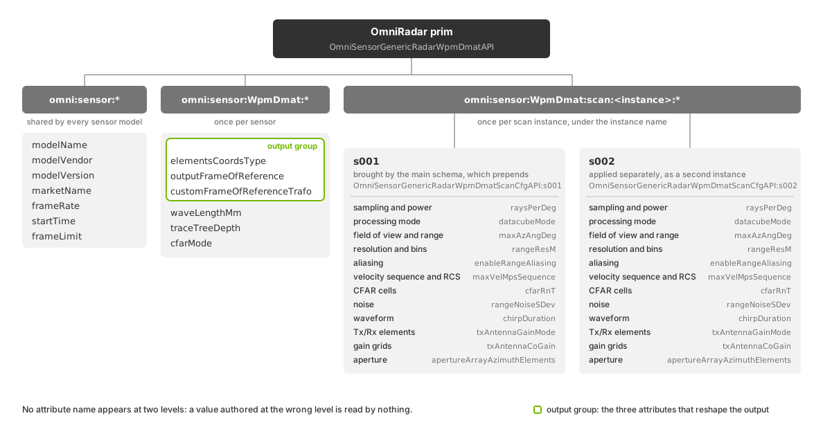
Shared sensor settings and radar-wide settings apply to all scans. Each scan instance has its own configuration attributes. The highlighted attributes control output coordinates and the reference frame.#
Scan instances#
OmniSensorGenericRadarWpmDmatAPI includes the scan-schema instance
OmniSensorGenericRadarWpmDmatScanCfgAPI:s001 with its defaults. This
satisfies the requirement for at least one scan. Each additional instance
adds per-scan attributes under its own name. The model discovers scans from
these attribute names; there is no separate scan-count attribute.
Scan names are compared in lowercase and sorted lexicographically. Names
that differ only in case configure the same scan. Each name must be an
identifier that does not start with a numeral. Use zero-padded names such
as s001 and s002 to preserve numeric order: s10 would otherwise
sort between s1 and s2.
The output’s scanIdx parameter reports the position in this order, from
zero: s001 is index 0 and s002 index 1. See
Run More Than One Scan Pattern for authoring and output verification.
Identification and rate#
The radar schema sets omni:sensor:modelName to "RadarWPMDMAT",
omni:sensor:frameRate to (20, 1) and omni:sensor:startTime to
(0, 1000). The start time is a rational offset in seconds; this default
is zero seconds. Vendor, market name and frame limit retain the shared
values "NVIDIA", "Generic" and 0. See
shared attributes
for their definitions.
omni:sensor:frameRate sets the scan rate as rational Hz
(numerator, denominator). The radar schema defaults to (20, 1):
20 scans per second. Fractional and positive sub-Hz rates are supported.
This rate is independent of the renderer’s step size.
Scan time advances by one scan period from omni:sensor:startTime.
Acquisition time is scan time plus the scan’s timeOffsetUsec delay,
in microseconds. The step’s delta_time advances the shared simulation clock;
see Frame rate, step and delivery.
Each returned frame covers a window of that clock and contains one scan. A scan fires when its acquisition time falls in the window. A time exactly on the boundary belongs to the later window. A step longer than the scan period can return several frames; inspect every frame.
Rays, scene motion, sensor pose and timestampNs use the acquisition time.
For a moving radar, the pose is interpolated between the frame window’s start
and end poses, reported in Outputs.
Scans take turns. After one fires, the next waits for the next scan time,
regardless of its delay. Two scans never share a scan time, and a missed scan
time is not made up later. A time window with no scan produces no radar frame.
A scan that fires but detects nothing is published with Counts[0] = 0
and its acquisition timestamp. See Outputs for handling it.
An authored rate of (0, 1) means unset. This is the shared base default,
not the radar schema’s default. The renderer uses its
default capture schedule;
the radar scans at the end of every capture and ignores timeOffsetUsec.
With multiple scans, frameRate is the combined scan rate, not the
repetition rate of each scan. See Run More Than One Scan Pattern for the
cycle and stepping procedure, and Sensor Scheduling for the
relationship between sensor rates, renderer steps and output delivery.
Output coordinates#
These attributes control output coordinates for all scans:
omni:sensor:WpmDmat:elementsCoordsType(token,CARTESIANorSPHERICAL, defaultSPHERICAL) is the coordinate system of theCoordinateschannel. Spherical rows are azimuth and elevation in degrees followed by range in meters; Cartesian rows are x, y and z in meters.omni:sensor:WpmDmat:outputFrameOfReference(token,SENSOR,WORLDorCUSTOM, defaultSENSOR) is the frame of the detection coordinates. Doppler remains sensor-relative and scan angular limits remain in the sensor frame. It applies to either coordinate representation: a spherical detection in theWORLDframe has its azimuth and elevation measured about the world axes, not about the sensor.omni:sensor:WpmDmat:customFrameOfReferenceTrafo(float[], default[0, 0, 0, 0, 0, 0]) is the custom frame as[x, y, z, roll, pitch, yaw]: the position in meters and the three angles in radians. It is read only whenoutputFrameOfReferenceisCUSTOM.
Check the output’s coordsType and frameOfReference parameters before
interpreting Coordinates. Outputs lists their values and units.
The same choices use different attribute prefixes on
core lidar.
Note
The model re-reads all three attributes whenever it accepts a parameter update and applies the new coordinate system, frame of reference and custom transform from the next frame on. A frame already in flight finishes with the values it started with. Runtime updates covers the rest of the prim.
Select the output channels on the PointCloud RenderVar, separately
from these coordinate controls. See requesting channels and the radar’s
channel descriptions.
Sensor-level parameters#
The following attributes under omni:sensor:WpmDmat: apply to all scans.
omni:sensor:WpmDmat:waveLengthMm (float, default 3.9) is the
operating wavelength in millimeters, shared by every scan in both processing
modes. It sets the wavelength for propagation, antenna gain, material response
and RCS normalization. WAVEFORM processing derives its carrier frequency
from this value. A published carrier frequency is authored as this wavelength;
Choose Parameter Values shows the conversion.
The non-visual materials of the scene are evaluated at this wavelength; Non-Visual Sensor Materials covers how the labels are authored.
omni:sensor:WpmDmat:traceTreeDepth (uint, default 3) limits surface
interactions per propagation path. Each interaction can contribute energy to
the receiver, with delay determined by the round-trip path length; see
Glossary.
A depth of 1 restricts propagation to a single surface interaction.
Higher depths allow indirect paths and ghost detections at greater tracing
cost. See Validate a Parameterization for the multipath check.
The model traces to the largest maxRangeM among its scans. Other
propagation limits are fixed; see Limitations.
omni:sensor:WpmDmat:cfarMode (token, 2D or 4D, default 2D)
selects how many dimensions the detection test covers for the sensor’s FAST
scans. The model gathers contributions into a range-velocity-azimuth-elevation
detection matrix and extracts detections from the cells that pass a threshold,
as CFAR describes. In 2D
the test runs over range-velocity cells, and a cell that passes yields at most
one detection, taken from its strongest azimuth-elevation bin, so two targets
in the same range-velocity cell cannot be separated in angle. In 4D every
cell of the matrix is tested on its own. A WAVEFORM scan always runs the
four-dimensional test, regardless of cfarMode.
One CFAR mode governs every FAST scan. cfarMode is a sensor-level
attribute while the test and guard cell counts it switches on are per scan, so a
sensor whose FAST scans want different dimensionality cannot express that.
The azimuth and elevation cell counts of every FAST scan are inert while
cfarMode is 2D; a WAVEFORM scan always reads them.
Per-scan parameters by mode#
Author per-scan controls under
omni:sensor:WpmDmat:scan:<instance>:<name>. The processing mode determines
which controls apply.
datacubeMode is a token that selects the detection-processing mode:
FAST(default) maps each contribution directly into range, velocity, azimuth and elevation bins, then extracts detections from those bins.WAVEFORMgenerates a sampled signal using the chirp, sampling, padding, window and aperture settings, then extracts detections from its spectrum. A chirp is one frequency-swept pulse. This mode includes signal-sampling effects and the main lobe and sidelobes produced by transforming a finite-duration signal.
All scans on one sensor prim must use the same mode. Mixing FAST and
WAVEFORM scans is not supported.
The table shows which controls apply to each mode:
Attribute group |
|
|
|---|---|---|
Sampling and limits: |
read |
read |
Aliasing switches: |
read; folds when on |
read; discards when off, folds nothing |
Resolution and bins: |
read |
ignored |
|
read; folds radial velocity |
ignored; bounds come from the waveform |
RCS calibration and the eight measurement-noise attributes |
read |
read |
CFAR range and velocity cells, |
read |
read |
CFAR azimuth and elevation cells |
read when |
always read |
Waveform attributes: samples, padding, chirp,
|
ignored |
read |
Receiving aperture: the six |
ignored |
read |
Tx and Rx element attributes |
gated by |
the same |
waveformMode (uint) selects how a WAVEFORM scan computes its spectrum:
0(default): evaluate each contribution separately.1: evaluate each bin separately.2: accumulate sampled signal values, then transform the accumulated signal.
Modes 0 and 1 are intended to produce equivalent results. Their
performance depends on the scene; neither is consistently faster. Mode 2
is not guaranteed to produce equivalent results. FAST scans ignore
waveformMode.
Use the following controls for each effect:
Phenomenon |
Primary controls |
|---|---|
Field of view and antenna sensitivity |
|
Return strength and RCS |
the non-visual materials, |
Multipath and ghost detections |
|
Motion and Doppler |
scene motion and the renderer’s motion BVH, |
Range, angle and velocity ambiguity |
|
Detection and false alarms |
|
Fidelity and frame time |
|
Scan sampling and power#
raysPerDeg(float, default8.0) is the geometric sampling density of the scan, in rays per degree across its field of view; the total ray count also followsmaxAzAngDegandmaxElAngDeg. Raising it improves geometric coverage at more cost per frame. It is not an angular-resolution setting: it does not sharpen the configured angular resolution, so tune it for stable coverage at an acceptable frame time.powerFactor(float, default1.0) is a unitless scaling of the scan’s transmit power. It scales contribution strength before detection and is not a value in watts.timeOffsetUsec(uint, default0) delays this scan’s acquisition by that many microseconds after its scan time. The frame rate says what the delayed time moves and when the delay is not applied.detValFromBinIdx(bool, defaultfalse) makes aFASTscan report range and radial velocity from the index of the detection bin instead of the contribution-weighted values within it.elevMode(token, defaultFULL_EL) is the scan’s elevation coverage:FULL_ELreports positive and negative elevation,NO_ELzero elevation for every detection,POS_ELnon-negative values only.
Field of view, range and resolution#
These are the values most often published for a real sensor, and the first ones to copy from a specification sheet; Build a Profile from a Spec Sheet maps the fields.
maxRangeM (float, default 200) is the scan’s maximum unambiguous
range, in meters. Contributions beyond it are discarded or folded, as
enableRangeAliasing decides. The sensor traces the scene out to the largest
maxRangeM among its scans.
maxAzAngDeg (float, default 66) and maxElAngDeg (float,
default 20) are positive half-angles in degrees. The azimuth field of view
runs from -maxAzAngDeg to +maxAzAngDeg, so the total is twice the value,
and the elevation field of view is symmetric in the same way, subject to
elevMode. A 150° field of view is therefore authored as 75; Choose
Parameter Values describes the transcription mistake
and its symptom. Every antenna gain profile is zero outside these limits, and
the default profile, COSINE_FALLOFF, falls to zero at the limit itself;
refer to the antenna.
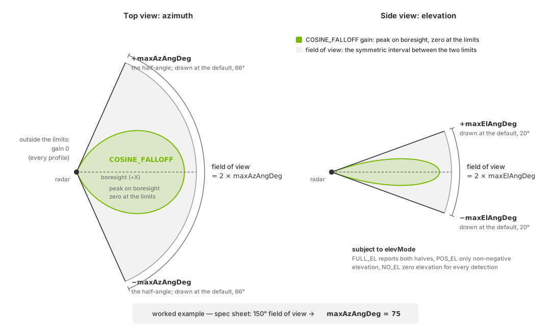
The angular limits are half-angles. The field of view is the symmetric
interval from the negative to the positive half-angle in each direction, and
the COSINE_FALLOFF gain profile falls to zero at the limits, so a
specification sheet’s 150° field of view is authored as maxAzAngDeg = 75.#
rangeResM (float, default 0.4 m), velResMps (float, default
0.147 m/s), boreAzResDeg (float, default 1.3 degrees) and
boreElResDeg (float, default 5.0 degrees) are the scan’s separation and bin
resolution in range, radial velocity, and azimuth and elevation at boresight,
the sensor’s look direction, where azimuth and elevation are zero. They are
active in FAST mode when binsFromSpec is true, where they decide how
finely the detection matrix is divided.
The four resolution attributes control detection-matrix bin sizes. Target
separation also depends on placement within bins, return strength and detection
filtering. The noise attributes add measurement noise; they do not
set resolution. Zero noise does not remove binning or estimation error.
Angular separation in a FAST scan also needs cfarMode set to 4D
(cfarMode).
Bins#
The bin counts of a FAST scan’s detection matrix are either derived or
explicit. With binsFromSpec (bool, default true) the model derives
the range, velocity, azimuth and elevation bin counts from the configured
limits and the four resolution attributes, and ignores the explicit counts. With
it false, rBins (uint, default 112), vBins (uint, default
160), azBins (uint, default 12) and elBins (uint,
default 2) are read as the counts. A WAVEFORM scan reads none of the
five; its matrix is sized by the padding attributes instead.
Aliasing and the unambiguous intervals#
In FAST mode, contributions outside the configured range, velocity or
angular intervals are discarded or folded before detection processing:
enableRangeAliasing(bool, defaultfalse): when false, contributions beyondmaxRangeMare discarded, in either processing mode. When true, aFASTscan folds them into the unambiguous range, so a target beyondmaxRangeMcomes back at a plausible shorter range.enAngAliasing(bool, defaultfalse): when false, contributions outside the azimuth and elevation limits are discarded, in either mode. When true, aFASTscan folds them into the angular interval.Radial velocity has no switch; a
FASTscan always folds it (velocity sequence).
In WAVEFORM mode, ambiguity results from waveform sampling. With frequencyStepBetweenChirps at its
default of 0, its radial velocity comes back within
±λ / (4 × T) before velocity noise is added, where λ is waveLengthMm
converted to meters and T is the selected chirpRepetitionTimeSequence entry;
at the schema defaults that bound is about ±27.9 m/s. The reported
minVelMps and maxVelMps describe this waveform velocity envelope before
noise. Nonzero frequencyStepBetweenChirps couples range and velocity and
can make the bounds asymmetric.
The output does not identify folded detections; they contain finite range, velocity and RCS values like other detections. Enable range or angular aliasing only when the real operating mode has the corresponding ambiguity; Choose Parameter Values places the switches among the values that describe the device rather than the simulation.
Velocity sequence and RCS calibration#
maxVelMpsSequence (float[], default [50.0, 55.0]) is a non-empty
sequence of finite, positive maximum unambiguous radial velocities, in meters
per second, for a device whose velocity ambiguity changes from frame to frame.
The active entry defines the symmetric interval into which a FAST scan
folds Doppler values, and the frame reports it as maxVelMps, with
minVelMps as its negative. WAVEFORM scans derive their bounds from the
waveform instead. An empty list, or an entry that is not finite and positive,
fails validation whichever processing mode the scan uses; Runtime updates
says what a rejected update does.
Each scan advances its own sequence only when it fires: maxVelMpsSequence
for FAST, chirpRepetitionTimeSequence for WAVEFORM. Firings of
other scans and time windows with no acquisition leave its entry unchanged. Every
sequence starts at its first entry, and the scan cycle at its first scan, when
the sensor is created; both restart there after every accepted attribute
update (Runtime updates) and whenever the renderer clears
its accumulated rendering history, as it does on
reset() (ovrtx_reset() in C) and after new
scene content has streamed in (warm-up). With two scans and a two-entry
sequence, each scan therefore visits both entries in order. Read the active
bounds from the frame’s minVelMps and maxVelMps params; Outputs lists the params.
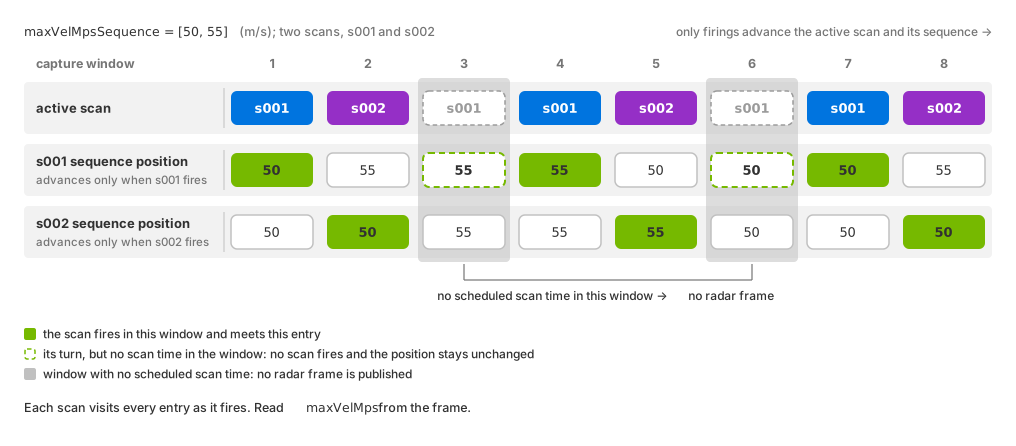
Firings advance the scan cycle and only the firing scan’s velocity sequence. Both scans visit 50 and 55 m/s in order. Windows with no acquisition publish no radar frame and leave the pending scan and both sequence positions unchanged.#
rcsTuningCoefficients (float[], default [-12, 150, 0.0]) must hold
exactly three RCS calibration values, where RCS, the radar cross section, is
the per-detection measure of how detectable a target is, in dBsm:
Element 0 is the minimum accepted RCS in dBsm. After the clamp the RCS channel describes, the model drops the detections whose RCS is below this minimum.
Element 1 is a scale applied to the RCS before its conversion to dBsm, where
1means no scaling. The default,150, is not a neutral value: a calibration against measured return strength starts from the default, not from1.Element 2 is the standard deviation of the noise added to the RCS, in dBsm, where
0adds no noise.
The RCS a detection carries depends on the materials, the antenna gains, the distance and the incidence geometry as well as on these coefficients; Validate a Parameterization describes the material and antenna check.
CFAR#
CFAR, constant false alarm rate, is the test that decides which cells of the
detection matrix become detections. For each candidate cell the model estimates
the local background from the cells around it, the test cells, leaving out a
ring of guard cells immediately around the candidate so that the candidate’s
own energy does not raise its own threshold. The sensor-level
cfarMode decides
whether that neighborhood covers range and velocity only, or all four
dimensions, for a FAST scan; a WAVEFORM scan always uses all four.
cfarRnT,cfarVnT,cfarAznTandcfarElnT(uint, default1each) are the numbers of test cells on each side of the candidate in range, velocity, azimuth and elevation, andcfarRnG,cfarVnG,cfarAznGandcfarElnG(uint, default0each) the numbers of guard cells excluded. The azimuth and elevation counts are read whencfarModeis4D, and always by aWAVEFORMscan.cfarOffset(float, default1.0) multiplies the estimated background to form the detection threshold. Raising it reduces false alarms and increases missed detections.cfarMinVal(float, default7e-17) is an absolute floor: a candidate cell whose value does not exceed it is discarded before the threshold is formed, whatever its neighborhood holds.cfarNoiseMeanandcfarNoiseSDev(float, default0.0each) describe noise that the model adds, as a magnitude, to the test cells while it estimates the background. The noise therefore raises the threshold; it never adds energy to the candidate, so it never creates a detection in a cell that received no contribution.
Note
Indirect energy in neighboring cells can raise the CFAR threshold and suppress a direct-path detection. In 2D mode, a range-velocity cell produces at most one detection, using its strongest angular bin. A stronger indirect return can therefore determine the reported angle. Cells without contributions cannot pass CFAR, so an empty scene cannot test false alarms. See Validate a Parameterization for the filtering check.
Noise#
These attributes add noise to the measured range, velocity and angles. They are independent of the resolution controls. All eight default to zero, so no measurement noise is added. Binning and estimation can still introduce error.
azimuthRadNoiseMeanandazimuthRadNoiseSDev: the mean and standard deviation of the azimuth angle noise at boresight, in radians.elevationRadNoiseMeanandelevationRadNoiseSDev: the same for elevation at boresight, in radians.velocityNoiseMeanandvelocityNoiseSDev: the same for radial velocity, in meters per second.rangeNoiseMeanandrangeNoiseSDev: the same for range, in meters.
The four angle values are boresight values. At boresight the reported angle is offset by the mean and spreads by the standard deviation you authored. Away from boresight the same noise moves the angle further, by a factor of about 1/cos(angle) for small noise: 1.4 times as far at 45°, twice as far at 60°. Range and velocity noise are added to the measured value directly, in meters and meters per second.
All eight are float; a mean may be any value and a standard deviation is
non-negative. Where the values come from is on Choose Parameter Values.
Waveform processing#
A WAVEFORM scan reads the attributes below; a FAST scan ignores them.
Both modes use the sensor-level waveLengthMm for their wavelength.
slowTimeSamples(uint, default379) andfastTimeSamples(uint, default625) are the numbers of slow-time samples, across the chirps of a frame, and of fast-time samples, within a chirp.chirpDuration(float, default25e-6) is the duration of one chirp in seconds,chirpBandwidth(float, default375e6) its bandwidth in hertz.chirpRepetitionTimeSequence(float[], default[35e-6]) supplies the times from one chirp to the next, in seconds. The sequence must be non-empty, with finite positive entries. On aWAVEFORMscan each entry must also be at leastchirpDurationand must differ fromfrequencyStepBetweenChirps×chirpDuration/chirpBandwidth; at the default step of0every positive entry qualifies. One entry holds for every chirp of a firing; the next firing of that scan uses the next entry, wrapping at the end. A single entry gives fixed timing.frequencyStepBetweenChirps(float, default0.0) is the frequency step between consecutive chirps, in hertz. At the default of zero the velocity ambiguity of the scan is the symmetric bound given under aliasing; a nonzero step of either sign makes the reportedminVelMpsandmaxVelMpsasymmetric, as described there.supportFactor(float, default1.0) is the spectral support of a contribution in units of main-lobe width;1is one main lobe.windowSlowTimeandwindowFastTime(token, defaultRECT) are the separable window functions for slow-time (Doppler) and fast-time (range) processing, from the shared token setRECT,HANN,HAMMINGandBLACKMANthat the Tx, Rx and aperture windows use as well.
azimuthPaddingSamples (uint, default 128),
elevationPaddingSamples (uint, default 32),
slowTimePaddingSamples (uint, default 512) and
fastTimePaddingSamples (uint, default 1024) are transform lengths:
each is the number of samples the scan transforms over in that dimension
after zero padding, and together they size the WAVEFORM scan’s detection
matrix. Author each at least as large as the sample or element count it
transforms: the slow-time padding at least slowTimeSamples, the fast-time
padding at least fastTimeSamples, and the azimuth and elevation padding at
least the aperture’s element counts. The defaults satisfy this.
See the 77 GHz waveform example for these controls in use.
Antenna configuration#
The model gives a scan a transmitting (Tx) element, a receiving (Rx) element
and, for WAVEFORM processing, a receiving aperture. Each element has its own
gain profile over direction, and the profiles shape how strongly a contribution
from a given direction counts.
txAntennaGainMode and rxAntennaGainMode (token, default
COSINE_FALLOFF) select the gain profile of the Tx and the Rx element from
four modes. CONSTANT is a uniform gain over the scan’s field of view.
COSINE_FALLOFF is highest at boresight and falls off as a cosine towards the
angular limits, reaching zero at the limit itself. CUSTOM interpolates a gain
grid you author, described below. PATCH_ARRAY_MODEL models a rectangular
patch array from the element counts, spacings, steering angles and windows
below, at the sensor’s waveLengthMm wavelength. Every profile is
zero outside the scan’s maxAzAngDeg and maxElAngDeg.
PATCH_ARRAY_MODEL uses separate transmit (tx*) and receive (rx*)
settings. Each set applies only when that side’s gain mode is
PATCH_ARRAY_MODEL:
Element counts:
txArrayAzimuthElementsandtxArrayElevationElements; receive equivalentsrxArrayAzimuthElementsandrxArrayElevationElements. Type:uint; default:0.Element spacing:
txAzimuthElementSpacingandtxElevationElementSpacing; receive equivalentsrxAzimuthElementSpacingandrxElevationElementSpacing. Type:float; units: meters; default:0.0.Array-factor windows:
txWindowAzimuthandtxWindowElevation; receive equivalentsrxWindowAzimuthandrxWindowElevation. Default:RECT; values use the shared window token set.Steering angles:
txAzimuthSteeringAngleDegandtxElevationSteeringAngleDeg; receive equivalentsrxAzimuthSteeringAngleDegandrxElevationSteeringAngleDeg. Units: degrees; default:0.0.
Transmit and receive attributes have the same types, defaults and behavior.
Warning
The element counts and spacings of the Tx element, the Rx element and the
receiving aperture all default to 0 or 0.0, while each requires a
positive value. The defaults are placeholders rather than a working array:
selecting PATCH_ARRAY_MODEL, or WAVEFORM processing, means authoring
the geometry as well. Left at zero, a PATCH_ARRAY_MODEL element has zero
gain in every direction, and a WAVEFORM scan whose aperture element
spacing is zero yields no detections.
Custom gain grids. CUSTOM gain mode interpolates element gain from
separate transmit and receive grids. Each grid uses four float[] arrays:
txAntennaAzDeg/rxAntennaAzDeg: azimuth angles in degrees, ordered from lowest to highest. Default:[-66.0, 66.0].txAntennaElDeg/rxAntennaElDeg: elevation angles in degrees, ordered from lowest to highest. Default:[-20.0, 20.0].txAntennaCoGain/rxAntennaCoGain: linear co-polarization gains at the grid points. Default:[0.8, 0.7, 0.6, 0.9].txAntennaCrossGain/rxAntennaCrossGain: linear cross-polarization gains at the grid points. Default:[0.2, 0.3, 0.4, 0.1].
Each gain array contains len(ElDeg) × len(AzDeg) values, ordered by
increasing elevation, then increasing azimuth within each elevation row.
The model adds the co- and cross-polarization gains at each grid point,
then interpolates the summed gain.
See Choose Parameter Values for choosing a gain mode from the available antenna data.
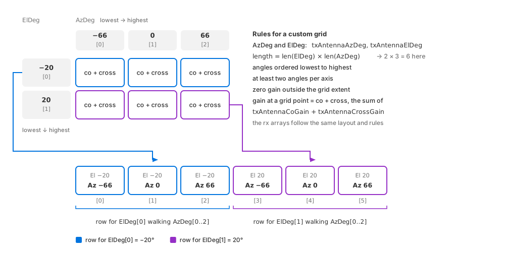
The layout of a custom gain array. The grid has one row per elevation angle and one column per azimuth angle; the array lists the rows one after the other, each walking the azimuth angles, and the gain at a grid point is the sum of its co- and cross-polarization values.#
Warning
Each angle vector must have at least two finite,
strictly increasing entries. Each gain array must hold exactly
len(ElDeg) × len(AzDeg) finite, nonnegative values. A grid that breaks
these rules is rejected and the reason is logged as an error. A valid grid
still has zero gain outside its angular extent, which can reduce detections
or suppress them entirely.
Receiving aperture. WAVEFORM processing uses a receiving aperture
configured separately from the transmit and receive elements. FAST scans
ignore these aperture settings.
The aperture can represent either:
A physical array with one transmitter and N receivers.
A virtual array formed by M transmitters and N receivers, equivalent to one transmitter with M × N receivers. The model assumes an L-shaped arrangement of physical transmit and receive elements, producing a uniform planar virtual array.
Configure the aperture with:
apertureArrayAzimuthElementsandapertureArrayElevationElements: element counts along each axis. Type:uint; default:0.apertureAzimuthElementSpacingandapertureElevationElementSpacing: element spacing in meters. Type:float; default:0.0.apertureWindowAzimuthandapertureWindowElevation: array windows. Type:token; default:RECT; values use the shared window token set.
Runtime updates#
The runtime-update procedure describes update outcomes and batch rejection. For this model:
The three output attributes, the sensor-level parameters and the per-scan parameters are re-read on every accepted update and take effect from the next frame; a frame already in flight finishes with the values it started with. That includes a change to the number of scans, to a scan’s
datacubeModeor to an antenna gain mode.An update that fails validation is logged as an error, and the model keeps its accepted configuration and its output layout: none of the edits in that update is applied, and the sensor goes on producing from the configuration that was in force before it.
To confirm that an edit reached the model, read the scan limits back from the output params as configuration verification describes; Outputs lists the params.
The model has no motion-compensation attribute: motion effects, radial
velocity above all, need the renderer’s motion BVH, a renderer-creation choice
(Motion BVH describes
AUTO and the recommended ENABLE mode; Simulate Moving Targets says what a radar
does without it). This and the other by-design limits of the model, the fixed
propagation limits among them, are listed on
Limitations.