

USD Attributes#
Author model and pattern attributes on the OmniGeneralSensor prim under
omni:sensor:GenericWpm:. The channels attribute belongs to the RenderVar.
Refer to Sensor API Schemas for complete
attribute declarations, types and schema defaults.
Sensor definition#
Instantiate an OmniGeneralSensor prim and apply OmniSensorGenericWpmAPI.
It includes the following APIs:
OmniSensorGenericWpmTxAPIdefines transmitter patterns and their ray and receiver assignments.OmniSensorGenericWpmRxAPIdefines receiver patterns.OmniSensorGenericWpmRayAPIdefines ray bundles.OmniSensorGenericWpmTxRxMappingAPIdefines explicit receiver groups.
The pattern APIs also include the Free, Grid and, for rays, Gaussian pattern attributes. All attributes are authored on the sensor prim. Separate named API instances are not needed.
Define at least one pattern for each role and assign a ray bundle and mapping
mode to each transmitter pattern. Empty schema arrays do not create a default
sensor. Connect the sensor to a RenderProduct through its camera relationship
and request one Contributions RenderVar through
orderedVars.
The example base authors the sensor and its output request. The USD Python tab
assumes an existing USD stage; add a pattern from How-To
to complete the sensor:
generic_wpm_base.usda, from the runnable Python example; the C example uses the same scene.##usda 1.0
(
defaultPrim = "World"
metersPerUnit = 1
upAxis = "Z"
timeCodesPerSecond = 10
)
def Xform "World"
{
def OmniGeneralSensor "Sensor" (
prepend apiSchemas = ["OmniSensorGenericWpmAPI"]
)
{
# Align the sensor's +X-forward basis with this Z-up world.
float3 xformOp:rotateXYZ = (90, 0, -90)
uniform token[] xformOpOrder = ["xformOp:rotateXYZ"]
double2 omni:sensor:frameRate = (10, 1)
uint omni:sensor:GenericWpm:maxBounces = 1
float omni:sensor:GenericWpm:maxHitDistanceM = 100
uint omni:sensor:GenericWpm:activeTxPatternIndex = 0
uint omni:sensor:GenericWpm:activeRxPatternIndex = 0
uint omni:sensor:GenericWpm:activeMappingPageIndex = 0
}
}
def Scope "Render"
{
def RenderProduct "GenericWpm"
{
rel camera = </World/Sensor>
rel orderedVars = [</Render/GenericWpm/Contributions>]
def RenderVar "Contributions"
{
uniform string sourceName = "Contributions"
# Empty selects the default contribution channels.
token[] channels = []
}
}
}
from pxr import Sdf, UsdGeom, UsdRender
UsdGeom.SetStageMetersPerUnit(stage, 1)
UsdGeom.SetStageUpAxis(stage, UsdGeom.Tokens.z)
stage.SetTimeCodesPerSecond(10)
world = UsdGeom.Xform.Define(stage, "/World").GetPrim()
stage.SetDefaultPrim(world)
sensor = stage.DefinePrim("/World/Sensor", "OmniGeneralSensor")
sensor.AddAppliedSchema("OmniSensorGenericWpmAPI")
# Align the sensor's +X-forward basis with this Z-up world.
sensor.CreateAttribute("xformOp:rotateXYZ", Sdf.ValueTypeNames.Float3, custom=False).Set((90, 0, -90))
sensor.CreateAttribute(
    "xformOpOrder", Sdf.ValueTypeNames.TokenArray, custom=False, variability=Sdf.VariabilityUniform
).Set(["xformOp:rotateXYZ"])
sensor.CreateAttribute("omni:sensor:frameRate", Sdf.ValueTypeNames.Double2, custom=False).Set((10, 1))
ns = "omni:sensor:GenericWpm:"
sensor.CreateAttribute(ns + "maxBounces", Sdf.ValueTypeNames.UInt, custom=False).Set(1)
sensor.CreateAttribute(ns + "maxHitDistanceM", Sdf.ValueTypeNames.Float, custom=False).Set(100)
for name in ("activeTxPatternIndex", "activeRxPatternIndex", "activeMappingPageIndex"):
    sensor.CreateAttribute(ns + name, Sdf.ValueTypeNames.UInt, custom=False).Set(0)

UsdGeom.Scope.Define(stage, "/Render")
product = UsdRender.Product.Define(stage, "/Render/GenericWpm")
product.CreateCameraRel().SetTargets(["/World/Sensor"])
product.CreateOrderedVarsRel().SetTargets(["/Render/GenericWpm/Contributions"])
output = UsdRender.Var.Define(stage, "/Render/GenericWpm/Contributions")
output.CreateSourceNameAttr("Contributions")
# Empty selects the default contribution channels.
output.GetPrim().CreateAttribute("channels", Sdf.ValueTypeNames.TokenArray, custom=False).Set([])
The pattern frames use the sensor coordinate convention described below; the prim’s placement follows Sensor Configuration.
One RenderProduct per independently configured sensor. Use independent products when configurations differ. Multiple sensor prims on one product form pose-only tiles whose configuration comes from the first sensor. Refer to tiled output.
Identification and scheduling#
Keep the schema’s model name and vendor unchanged: configuration acceptance
validates both. marketName remains a descriptive label. The schema sets these
four shared attributes:
USD declaration |
Description |
|---|---|
|
Selects this model on an |
|
The vendor required for configuration acceptance. |
|
A label for this parameterization. |
|
Complete captures per second, expressed as rational Hz. |
Refer to shared attributes and Sensor Scheduling for the remaining shared controls. Firing offsets describe events in each complete capture; they do not split a scan across successive frames.
Patterns and selection#
A pattern is an ordered collection of elements. The role determines what each element represents:
A transmitter pattern contains emitting elements, each with a position, orientation and firing offset.
A ray pattern, or ray bundle, contains samples emitted by each transmitter. Each sample has a local origin, direction and firing offset.
A receiver pattern contains receiving elements, each with a position and orientation. Receiver mapping chooses which of them participate in a path.
Store several patterns when different captures need different layouts. One transmitter pattern and one receiver pattern are active in a capture. The selected transmitter pattern assigns a ray bundle and a receiver-mapping rule to every transmitter it contains. These assignments belong to the pattern, not to individual transmitter elements. See Switch Stored Patterns for a complete recipe.
Together with the propagation controls, these patterns and receiver mappings form the trace definition. It specifies which rays to launch, which receiver connections to evaluate and how far to follow paths through the scene:
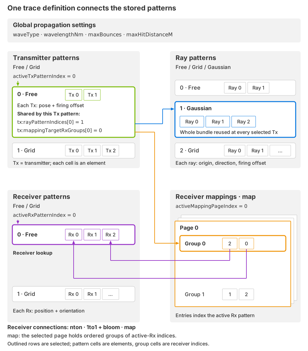
A trace definition combines propagation settings with selected geometry and receiver connections. Each transmitter, ray or receiver row is a stored pattern; its cells are elements. The selected transmitter pattern shares one ray bundle and one receiver-mapping rule across all its elements. Explicit mapping selects a page, then a group whose entries identify receivers in the selected receiver pattern. Schematic, not to scale.#
Pattern and element axes are logical dimensions; a Free pattern does not have to place its elements on a spatial grid. Mapping pages add a page axis to ordered receiver groups. Use the ray bundle’s angular distribution to choose where directions are sampled; Directivity and ray sampling illustrates this choice. Angular sampling does not provide antenna-gain tables or per-ray weights.
Each role has its own ordered list of patterns. An index into the transmitter list does not select the same-numbered receiver or ray pattern. A selected pattern with two transmitters and a bundle of three rays emits six rays: three at each transmitter pose. Receiver connections and bounce capacity determine how many contribution slots those rays can produce. Follow an emitted ray through scene hits and receiver connections in Paths and contributions.
USD declaration |
Description |
|---|---|
token[] omni:sensor:GenericWpm:tx:patternTypes = [] |
Transmitter alternatives, using |
token[] omni:sensor:GenericWpm:rx:patternTypes = [] |
Receiver alternatives, using |
token[] omni:sensor:GenericWpm:ray:patternTypes = [] |
Ray-bundle alternatives, using |
uint[] omni:sensor:GenericWpm:tx:rayPatternIndices = [] |
One valid index into |
uint omni:sensor:GenericWpm:activeTxPatternIndex = 0 |
Selects the active transmitter pattern. |
uint omni:sensor:GenericWpm:activeRxPatternIndex = 0 |
Independently selects the active receiver pattern. |
uint omni:sensor:GenericWpm:activeMappingPageIndex = 0 |
Selects the mapping page in |
There is no separate active-ray selector. Changing activeTxPatternIndex
also selects the bundle assigned by tx:rayPatternIndices.
Pattern data is stored in flat family arrays. Each occurrence of a family in
patternTypes consumes its next family row. For ["free", "grid", "free"],
the lookup is:
Role-pattern index |
Family |
Family row |
|---|---|---|
0 |
|
Free row 0, whose count identifies the first group of packed poses. |
1 |
|
Grid row 0, whose dimensions generate its elements. |
2 |
|
Free row 1, whose poses follow Free row 0’s elements. |
Selectors and tx:rayPatternIndices address role-pattern indices. Family rows
locate the data used to construct those patterns; element indices identify
transmitters, receivers or rays inside one pattern. These three indices are
distinct.
Coordinate frames#
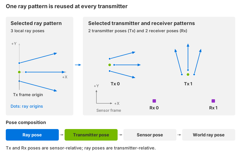
The selected ray bundle is reused at each transmitter pose. Its local origins and directions move with that transmitter. Receiver poses are independent of the transmitter poses. Schematic, not to scale.#
Transmitter and receiver poses are relative to the sensor. Ray poses are
relative to the transmitter. Positions must be finite and are in meters.
Orientations are finite unit quaternions in (x, y, z, w) order;
identity is (0, 0, 0, 1).
Local +X is forward. A ray orientation rotates +X into its emission direction.
For Free patterns, each element has its own pose. For Grid and Gaussian patterns, the pose transforms the generated pattern. Ray geometry is composed with the transmitter pose and then with the sensor prim’s transform and motion.
For example, rotating one transmitter rotates its entire ray bundle; it does not change the stored local ray directions. A nonzero ray origin offsets the emission point from that transmitter. Receiver orientation defines the frame used by receiver-relative output channels; it does not author a receiver gain pattern. Refer to output channels for the coordinate frame of each reported position.
Free patterns#
Free patterns explicitly place individual transmitters, receivers or rays. Use them for irregular layouts or measured element positions. See Connect Independent Transmitters and Receivers for a complete recipe.
The prefix is freePatterns:<role>:, where <role> is tx, rx or
ray. For example, transmitter positions use
omni:sensor:GenericWpm:freePatterns:tx:positions.
USD declaration |
Description |
|---|---|
uint[] omni:sensor:GenericWpm:freePatterns:tx:numElementsPerPattern = []uint[] omni:sensor:GenericWpm:freePatterns:rx:numElementsPerPattern = []uint[] omni:sensor:GenericWpm:freePatterns:ray:numElementsPerPattern = [] |
One positive element count per Free pattern. Counts partition the packed pose arrays. |
float3[] omni:sensor:GenericWpm:freePatterns:tx:positions = []float3[] omni:sensor:GenericWpm:freePatterns:rx:positions = []float3[] omni:sensor:GenericWpm:freePatterns:ray:positions = [] |
One finite position per element, in meters. |
float4[] omni:sensor:GenericWpm:freePatterns:tx:orientations = []float4[] omni:sensor:GenericWpm:freePatterns:rx:orientations = []float4[] omni:sensor:GenericWpm:freePatterns:ray:orientations = [] |
One unit xyzw quaternion per element. |
Both pose arrays must contain the sum of numElementsPerPattern.
For counts [2, 1], the first two poses belong to Free pattern 0 and the third
to Free pattern 1. Empty poses do not imply an origin or identity orientation.
Firing-time attributes for Tx and ray elements are described under
Firing times.
Grid patterns#
Grid patterns generate regularly spaced elements. The prefix is
gridPatterns:<role>: for tx, rx or ray.
Every geometry array below must have one entry per Grid pattern of that role. See Sample a Depth Grid for a complete recipe.
USD declaration |
Description |
|---|---|
token[] omni:sensor:GenericWpm:gridPatterns:tx:modes = []token[] omni:sensor:GenericWpm:gridPatterns:rx:modes = []token[] omni:sensor:GenericWpm:gridPatterns:ray:modes = [] |
Geometry: |
uint[] omni:sensor:GenericWpm:gridPatterns:tx:numRows = []uint[] omni:sensor:GenericWpm:gridPatterns:rx:numRows = []uint[] omni:sensor:GenericWpm:gridPatterns:ray:numRows = []uint[] omni:sensor:GenericWpm:gridPatterns:tx:numCols = []uint[] omni:sensor:GenericWpm:gridPatterns:rx:numCols = []uint[] omni:sensor:GenericWpm:gridPatterns:ray:numCols = [] |
Positive row and column counts. Their product is the pattern’s element count. |
float[] omni:sensor:GenericWpm:gridPatterns:tx:startRowUnits = []float[] omni:sensor:GenericWpm:gridPatterns:rx:startRowUnits = []float[] omni:sensor:GenericWpm:gridPatterns:ray:startRowUnits = []float[] omni:sensor:GenericWpm:gridPatterns:tx:endRowUnits = []float[] omni:sensor:GenericWpm:gridPatterns:rx:endRowUnits = []float[] omni:sensor:GenericWpm:gridPatterns:ray:endRowUnits = [] |
First and last row coordinates. Units depend on the grid mode. |
float[] omni:sensor:GenericWpm:gridPatterns:tx:startColUnits = []float[] omni:sensor:GenericWpm:gridPatterns:rx:startColUnits = []float[] omni:sensor:GenericWpm:gridPatterns:ray:startColUnits = []float[] omni:sensor:GenericWpm:gridPatterns:tx:endColUnits = []float[] omni:sensor:GenericWpm:gridPatterns:rx:endColUnits = []float[] omni:sensor:GenericWpm:gridPatterns:ray:endColUnits = [] |
First and last column coordinates. Units depend on the grid mode. |
token[] omni:sensor:GenericWpm:gridPatterns:tx:layouts = []token[] omni:sensor:GenericWpm:gridPatterns:rx:layouts = []token[] omni:sensor:GenericWpm:gridPatterns:ray:layouts = [] |
|
float3[] omni:sensor:GenericWpm:gridPatterns:tx:positions = []float3[] omni:sensor:GenericWpm:gridPatterns:rx:positions = []float3[] omni:sensor:GenericWpm:gridPatterns:ray:positions = [] |
Pattern origin in meters, in the role’s parent frame. |
float4[] omni:sensor:GenericWpm:gridPatterns:tx:orientations = []float4[] omni:sensor:GenericWpm:gridPatterns:rx:orientations = []float4[] omni:sensor:GenericWpm:gridPatterns:ray:orientations = [] |
Unit xyzw orientation applied to the generated pattern. |
The modes produce the following local geometry, before the pattern pose:
Mode |
Rows / columns |
Element geometry |
|---|---|---|
|
Elevation / azimuth, in degrees |
All origins coincide; orientations sample angular directions. |
|
Z / Y, in meters |
Origins span the YZ plane; all elements face +X. |
|
Height in meters / azimuth in degrees |
Origins lie along Z; orientations sample azimuth. Origins do not lie around a cylinder’s circumference. |
Nonperiodic axes include both endpoints. Full-circle azimuth excludes the duplicate endpoint; a singleton axis uses its start value. Equal and reversed spatial endpoints are supported. All spatial bounds must be finite.
Gaussian ray patterns#
Gaussian patterns sample horizontal and vertical ray angles independently.
They are available only for rays, under gaussianPatterns:ray:.
Each array has one entry per Gaussian bundle, except optional arrays that are
empty to use zero for every bundle. See Sample a Finite-Width Beam for a complete recipe.
USD declaration |
Description |
|---|---|
uint[] omni:sensor:GenericWpm:gaussianPatterns:ray:numElements = [] |
Required positive ray count. Exactly this many rays are generated. |
float3[] omni:sensor:GenericWpm:gaussianPatterns:ray:positions = [] |
Required bundle origin in meters, relative to the transmitter. |
float4[] omni:sensor:GenericWpm:gaussianPatterns:ray:orientations = [] |
Required unit xyzw orientation of the bundle. |
uint[] omni:sensor:GenericWpm:gaussianPatterns:ray:seeds = [] |
Optional seed for repeatable angular samples. Empty means zero. |
float[] omni:sensor:GenericWpm:gaussianPatterns:ray:stdDevsHorizontal = [] |
Optional horizontal angular standard deviation in degrees. Finite and nonnegative; empty means zero. |
float[] omni:sensor:GenericWpm:gaussianPatterns:ray:stdDevsVertical = [] |
Optional vertical angular standard deviation in degrees. Finite and nonnegative; empty means zero. |
The spreads are standard deviations, not field-of-view bounds. Zero spread
retains the authored count as coincident rays; it does not collapse the bundle.
A seed makes the angular samples repeatable for the same configuration.
sourceDivergence separately controls traced beam
divergence in radians.
Receiver mapping#
Receiver mapping is configured per transmitter pattern. Define receiver poses first, then choose which receivers each path can contribute to. Connectivity does not move a receiver, change its orientation or add emitted rays. Refer to Connect Independent Transmitters and Receivers for a complete recipe.
USD declaration |
Description |
|---|---|
token[] omni:sensor:GenericWpm:tx:mappingModes = [] |
Required mode per transmitter pattern: |
uint[] omni:sensor:GenericWpm:tx:mappingBloomFactors = [] |
Optional neighborhood radius 0–7 per transmitter pattern, used only by |
uint[] omni:sensor:GenericWpm:tx:mappingTargetRxGroups = [] |
Page-local group index per transmitter pattern. Required at full Tx-pattern length if any stored pattern uses |
nton connects each path to every active receiver, up to 255 receivers.
It is useful when all receiver positions must participate.
1to1 requires equal active transmitter and receiver counts. With zero bloom,
it pairs equal flat indices, giving one receiver per transmitter. This does not
require co-located poses or matching grid cells.
Nonzero bloom selects a square receiver neighborhood centered on the
transmitter’s grid row and column, with groupSize = (2 * bloom + 1)^2.
Both patterns must be grids with matching row and column counts. Each grid’s
layout determines its flat indices, so the center receiver’s flat index can
differ from the transmitter’s when their layouts differ. Slot order is row
offset then column offset, from -bloom to +bloom; radius 1 puts the center
receiver in slot 4.
Rows clip at boundaries. Columns wrap only for a full-circle receiver grid,
which must be at least 2 * bloom + 1 columns wide. Clipped neighbors remain
invalid slots. Bloom changes receiver connectivity, not emitted ray count.
map connects each path to an explicit ordered receiver group. All elements
of the selected transmitter pattern use that group. Mapping pages are packed
under txRxMappings::
USD declaration |
Description |
|---|---|
uint[] omni:sensor:GenericWpm:txRxMappings:numRxGroupsPerPages = [] |
Positive number of groups per page. The sum equals the length of |
uint[] omni:sensor:GenericWpm:txRxMappings:numRxPerGroups = [] |
Receiver-slot count per group, each 1–255. The sum equals the length of |
uint[] omni:sensor:GenericWpm:txRxMappings:rxIndices = [] |
Packed, ordered receiver IDs. IDs are local to the active receiver pattern; duplicates remain distinct slots. |
activeMappingPageIndex chooses the page and
tx:mappingTargetRxGroups[activeTxPatternIndex] chooses a group within it.
Receiver IDs never address a global concatenation of stored receiver patterns.
Every ID on the selected page must fit the active receiver count, including
groups the selected transmitter does not use.
Inactive pages must have valid partitions but need not fit the active receiver pattern. An inactive transmitter’s group selector must fit at least one stored page, not necessarily the current page.
Firing times#
Transmitter offsets are relative to capture start. Ray offsets are relative to their transmitter’s firing time. The final firing offset is their sum. Receivers do not have firing offsets. See Configure a Full-Circle Scan for a complete recipe.
For example, a transmitter offset of 1,000,000 ns and a ray offset of
250,000 ns fire that ray 1,250,000 ns after capture start. Every contribution
from that emitted path carries the same firing offset, regardless of its
bounce or receiver. The output reports it as DeltaTimeNs; its exact
timestamp reference is on Outputs.
USD declaration |
Description |
|---|---|
uint[] omni:sensor:GenericWpm:freePatterns:tx:timeOffsetsNs = [] |
One capture-relative offset per packed Free transmitter element. |
uint[] omni:sensor:GenericWpm:freePatterns:ray:timeOffsetsNs = [] |
One transmitter-relative offset per packed Free ray. |
uint[] omni:sensor:GenericWpm:gridPatterns:tx:startTimeOffsetsNs = []uint[] omni:sensor:GenericWpm:gridPatterns:tx:endTimeOffsetsNs = [] |
First/last capture-relative offsets, one pair per transmitter grid. |
uint[] omni:sensor:GenericWpm:gridPatterns:ray:startTimeOffsetsNs = []uint[] omni:sensor:GenericWpm:gridPatterns:ray:endTimeOffsetsNs = [] |
First/last transmitter-relative offsets, one pair per ray grid. |
uint[] omni:sensor:GenericWpm:gaussianPatterns:ray:globalTimeOffsetsNs = [] |
One transmitter-relative offset per Gaussian bundle, applied to every ray. It is not an absolute or sensor-global timestamp. |
All offsets are nanoseconds. Each timing array may be empty for zero or must
have its full length. Grid end times must not precede start times.
For element ordinal i in traversal order and count n > 1, the offset is
start + floor((end - start) * i / (n - 1)). A singleton uses start.
This includes both timing endpoints even when the angular grid wraps.
Each authored offset is an unsigned 32-bit value. Transmitter and ray offsets are widened before addition, so their intended sum can exceed 32 bits.
Firing offsets select sensor and scene poses through motion interpolation.
Each is clamped to its available interpolation interval: an offset outside
that interval uses the nearest endpoint pose. The full selected pattern is
still traced in the capture; offsets do not defer rays to a later capture.
DeltaTimeNs retains the summed firing offset without this motion clamping.
Firing offsets are not wave travel times. Mechanical propagation does not advance moving geometry by acoustic travel time.
Propagation controls#
These sensor-wide attributes apply to every selected pattern. Choose wave type and wavelength together; changing one does not convert the other. See Select Mechanical Propagation for a complete recipe.
USD declaration |
Description |
|---|---|
token omni:sensor:GenericWpm:waveType = "electroMagnetic" |
|
float omni:sensor:GenericWpm:wavelengthNm = 903 |
Positive operating wavelength in nanometers. Changing wave type does not convert this value. |
float omni:sensor:GenericWpm:bandwidthFactor = 0.15 |
Nonnegative, unitless spectral bandwidth factor. |
uint omni:sensor:GenericWpm:maxBounces = 3 |
Maximum material-hit evaluations along an emitted path, 1–255. Also sets the output bounce dimension. |
uint omni:sensor:GenericWpm:maxContributionRayDepth = 1 |
Maximum material evaluations between a bounce and a receiver, 0–255. |
float omni:sensor:GenericWpm:minHitDistanceM = 0.005 |
Nonnegative minimum hit distance for continuation rays, in meters. |
float omni:sensor:GenericWpm:minPrimaryHitDistanceM = 0.005 |
Nonnegative minimum primary-ray hit distance in meters. |
float omni:sensor:GenericWpm:maxHitDistanceM = 1000 |
Ray-hit search limit in meters; must exceed both minimum distances. |
float omni:sensor:GenericWpm:sourceDivergence = 0.001 |
Nonnegative beam-divergence angle in radians, independent of Gaussian sampling spread. |
float omni:sensor:GenericWpm:contributionRayRxHitOffsetM = 0.05 |
Nonnegative receiver-side acceptance distance for contribution rays, in meters. |
All floating-point controls must be finite. Non-visual materials are used when calculating responses. Refer to Non-Visual Sensor Materials. Mechanical-mode scope is listed under model limits.
maxBounces limits the emitted path’s scene hits. The connection from one
of those hits to a receiver has a separate material-evaluation limit,
maxContributionRayDepth. A value of zero still tests that connection for
occlusion: an intervening surface blocks it. A positive value allows material
evaluation along the connection; it does not add another dimension or more
bounce levels to the output. See Paths and contributions for the two parts of a path.
Array requirements#
Required family arrays have the lengths described above. Optional numeric
arrays are empty or full length; empty means zero, not singleton broadcasting.
For example, two Gaussian patterns accept seeds = [] or two seed values,
but not one. A family absent from a role’s patternTypes must have empty
arrays. Clear inherited family data when replacing that family.
All stored patterns and mapping partitions must remain structurally valid, including inactive choices. Compatibility of the active transmitter, receiver and mapping page is checked separately. Storing several valid alternatives does not mean every combination of selectors is valid.
Runtime updates#
Model controls, pattern geometry, counts and selectors can change while the sensor runs. Refer to Runtime Parameter Updates for publishing related writes together.
Each proposed configuration is accepted or rejected as a whole. Before the first valid configuration, the output is EMPTY. An invalid live edit retains the complete last accepted configuration, including model controls, patterns and selectors. The model continues tracing that configuration against the current scene and sensor motion; it does not freeze the previous output frame.
Separate attribute writes are not automatically atomic. Publish related edits together before rendering. Compare the output’s accepted selector parameters with the requested values, and check the renderer log for rejections. The runnable examples demonstrate coordinated updates and recovery.
Refer to Switch Stored Patterns for a complete accept/reject/recovery sequence. Read the accepted selector parameters and layout in the output; authored stage values alone do not prove acceptance.
Parameter validation#
The sensor definition check validates model controls and basic scheduler inputs. Pattern array structure and compatibility are checked when the complete sensor configuration is accepted. A successful model-controls check alone does not establish that a selected pattern is valid.
Define every required family array with its full cardinality, including inactive alternatives (array requirements).
Give each pose finite coordinates and a unit orientation (coordinate frames).
Keep the selected transmitter, receiver and mapping page compatible (receiver mapping).
Keep model controls within their finite ranges (propagation controls).
Keep total contribution capacity within the model’s bound (allocated capacity).