

Outputs#
The Radar generic wpmDmat model delivers one PointCloud composite output
per requesting RenderVar. It contains per-detection tensors, two automatically
included tensors and CPU-resident parameters describing the frame and scan.
See USD Attributes for output controls and
Sensor Outputs for mapping and container access.
Each entry represents a detection accepted by processing, rather than a ray hit. There is no per-emitter, per-echo or per-surface information. Each published radar frame contains one scan, which may have zero detections.
An object can produce multiple detections or none. Multipath can produce ghost
detections whose ranges follow the propagation path. RadialVelocityMs
measures direct-path line-of-sight motion or, for multipath returns, motion
projected along the propagation segments. See Radar generic wpmDmat model.
Requesting the output#
A radar scene needs a RenderProduct whose camera relationship names the
OmniRadar prim and whose orderedVars names a RenderVar with
sourceName = "PointCloud"; the RenderVar’s channels attribute lists the
tensors to produce. Output Configuration explains
RenderProducts, RenderVars and the channels attribute in general. The example below requests coordinates, radar cross section and radial
velocity. Omit RCS from channels when you do not need it.
#usda 1.0
    def "Render"
    {
        def "Products"
        {
            def RenderProduct "RadarProduct"
            {
                rel camera = </World/Radar>
                rel orderedVars = [<../../Vars/PointCloud>]
            }
        }

        def "Vars"
        {
            def RenderVar "PointCloud"
            {
                uniform string sourceName = "PointCloud"
                token[] channels = [
                    "Coordinates",
                    "Counts",
                    "RCS",
                    "RadialVelocityMs"
                ]
            }
        }
    }
from pxr import Gf, Sdf

world = stage.DefinePrim("/World", "Xform")

render = stage.DefinePrim("/World/Render", "")

products = stage.DefinePrim("/World/Render/Products", "")

radar_product = stage.DefinePrim("/World/Render/Products/RadarProduct", "RenderProduct")
radar_product.CreateRelationship("camera", custom=False).SetTargets(["/World/Radar"])
radar_product.CreateRelationship("orderedVars", custom=False).SetTargets(
    ["/World/Render/Vars/PointCloud"]
)

vars = stage.DefinePrim("/World/Render/Vars", "")

point_cloud = stage.DefinePrim("/World/Render/Vars/PointCloud", "RenderVar")
point_cloud.CreateAttribute(
    "sourceName", Sdf.ValueTypeNames.String, custom=False, variability=Sdf.VariabilityUniform
).Set("PointCloud")
point_cloud.CreateAttribute("channels", Sdf.ValueTypeNames.TokenArray, custom=False).Set(
    ["Coordinates", "Counts", "RCS", "RadialVelocityMs"]
)
The names you can list are Coordinates, RCS, TimeOffsetNs,
RadialVelocityMs and Flags. Counts and Flags are added whether
or not you list them, so the Counts entry the example scenes author is
permitted but not required. How the list is read, what an unknown name does
and several PointCloud RenderVars on one product are on channels.
Channels#
The table lists every channel a radar PointCloud can carry. Nmax is
the capacity of the per-detection tensors, the number of entries each of them
is allocated for. The model publishes it beside the channels as the
maxPoints param, and for this model it is the fixed detection cap
described below. The
entries a frame delivered are the first Counts[0] of them.
Channel |
Type |
Shape |
Unit |
Meaning |
|---|---|---|---|---|
|
|
|
detections |
Number of entries delivered this frame. Bounds every per-detection tensor. Always published. |
|
|
|
unitless |
Per-detection status bits. The |
|
|
|
m, or deg / deg / m |
Position of the detection in the configured representation and frame, packed component-first. Cartesian rows are x, y and z in meters; spherical rows, the default, are azimuth and elevation in degrees followed by range in meters. |
|
|
|
dBsm |
Radar cross section: a logarithmic measure, in decibel square meters, of how detectable the target is. The value depends on the scan’s RCS calibration attributes and scene. Compare the range of values across a frame when evaluating response. It is clamped to [-60, 60] dBsm; detections below the scan’s minimum accepted RCS are dropped (rcsTuningCoefficients). |
|
|
|
m/s |
Doppler radial velocity along the line of sight. Signed; approaching detections are negative. |
|
|
|
ns |
Time offset of the detection within the scan. |
RCS, dBsm and the other radar terms are defined in the
glossary; the RCS calibration attributes,
rcsTuningCoefficients among them, are on USD Attributes. The
subsections below say how to read each channel.
Counts, Flags and the detection cap#
Counts[0] gives the number of delivered entries. Read only slots
[0, Counts[0]); the tensor length is allocated capacity. See
reading a variable-size output.
A scan produced detections:
Counts[0]is the detection count.A scan produced no detections:
Counts[0]is0and the output still carries the scan’s parameters and acquisition timestamp.No scan fired: no radar frame is published. This occurs when the pending scan’s acquisition time falls outside the step’s time window, commonly when simulation steps are shorter than the radar’s scan period.
A scan can fire at time zero, so timestampNs = 0 is a valid acquisition
timestamp. See
stepping and delivery
for aligning steps with scans, and Sensor Scheduling for sensors
running at different rates.
Empty scans#
A scan with no detections publishes Counts[0] = 0. Its scan parameters,
including scanIdx, cycleCnt and timestampNs, still describe that
acquisition. Per-detection tensors retain their allocated capacity, but have
no delivered entries to read. Use Counts[0] to recognize an empty scan;
no RCS channel is needed for this check.
Validity flags#
Every delivered detection has the VALID bit set. No other flag bits are
set. Radar has no includeInvalidPoints
option and does not include invalid slots within [0, Counts[0]).
Test validity with Flags[i] & 0x40, as the radar examples do. Avoid an
exact comparison with 0x40 so the reader also works with models that set
additional bits. See validity flags.
Detection limit#
Each scan can report up to 2500 detections. Additional detections are dropped
without a saturation indicator. maxPoints and the per-detection tensor
shapes report this fixed capacity; Counts[0] bounds the entries to read.
See allocated capacity.
Coordinate controls#
omni:sensor:WpmDmat:elementsCoordsType selects the coordinate
representation; outputFrameOfReference selects the reference frame, and
customFrameOfReferenceTrafo supplies its pose when set to CUSTOM.
See coordinate controls
for tokens, units and defaults. The radar ignores the lidar’s omni:sensor:Core:*
attributes (namespaces).
The SENSOR frame uses ISO 8855 axes. Read coordsType and
frameOfReference from each output to identify the active settings,
particularly after a runtime update.
Coordinates is packed component-first: all the x values, then all the y,
then all the z (or all the azimuths, all the elevations, then all the
ranges), with the capacity as the step between components, not the delivered
count. The mapped tensor reports this as a shape of [3, Nmax]
with strides of [Nmax, 1]. Take the layout from the shape and strides
rather than from the channel’s name, because other models pack a channel of
the same name differently (Tensor layouts). Both example scenes author
CARTESIAN, which is why the Python example plots the delivered columns as
x, y, z points without a conversion.
RadialVelocityMs#
Approaching detections have negative RadialVelocityMs. To select moving
detections in either direction, threshold its absolute value. To distinguish
approaching and receding detections, retain the sign. The example’s steel
cube moves toward the radar by 1 m per step for ten steps and produces
negative values.
A FAST scan folds radial velocity into the interval the frame reports as
minVelMps to maxVelMps, so a value inside that interval can belong to
a faster target; aliasing and the unambiguous intervals explains the folding and the
WAVEFORM case.
Doppler from moving targets needs the renderer’s motion BVH (Motion BVH); the moving-targets how-to says what the model does without it and how to check that the switch was active.
Timestamps#
The TimeOffsetNs channel is delivered when requested and holds 0 for
every detection, because the model simulates each scan as a single instant.
A radar frame therefore carries no per-detection timing. The frame’s own
timing is in its params: timestampNs is the scan’s instant, and
frameStartTimeStampNs and frameEndTimeStampNs bound the frame’s time
window, which can be wider than that instant. Consistent with this, the model has no motion-compensation
attribute (Limitations).
The Lidar generic core model defines a channel of the same name differently (the lidar time offset); Model-specific channel semantics gives the rule.
Material identifiers#
The radar PointCloud has no MaterialId channel, and no other channel
or param names a material: the label a detection came from is not reported.
The labels and how to author them are on Non-Visual Sensor Materials.
Params#
A radar PointCloud carries CPU-resident parameters: thirteen shared with core lidar and
ten radar-specific scan parameters. The table below gives the radar semantics
for the shared parameters.
Param |
Type |
Shape |
Value |
|---|---|---|---|
|
|
|
The model’s frame counter. It never restarts and can skip values
between published scans when no acquisition occurs in an intervening
time window. It is not a count of delivered scans; use |
|
|
|
The scan’s acquisition time, in nanoseconds: its scan time plus the
selected scan’s |
|
|
|
|
|
|
|
|
|
|
|
|
|
|
|
Transform from the sensor frame to the application frame: a
homogeneous transform stored row by row, with a bottom row of
|
|
|
|
Start of this frame’s time window, in nanoseconds. The scan’s acquisition time can fall later in this window. |
|
|
|
Sensor position at that start, in meters, in the world frame. |
|
|
|
Sensor orientation at that start, as a world-frame unit quaternion ordered x, y, z, w. |
|
|
|
End of this frame’s time window, in nanoseconds. It does not move when
|
|
|
|
Sensor position at that end, in meters, in the world frame. |
|
|
|
Sensor orientation at that end, as a world-frame unit quaternion ordered x, y, z, w. |
|
|
|
The capacity |
The shared table on Sensor Outputs lists the full enumerations of
modality, frameOfReference and coordsType.
Without the motion BVH the scene does not move within a frame, while the radar
itself still does: frameStartPosM, frameStartOrientation,
frameEndPosM and frameEndOrientation are its poses at the start and
the end of the frame’s time window, the rays fire from its pose at the scan’s
acquisition time, frameStartTimeStampNs and frameEndTimeStampNs bound
that window, and RadialVelocityMs still reflects the radar’s own movement
between frames. The model publishes
neither motionCompensationState nor compactionType, the two lidar-only
params: it has no motion compensation (Limitations), and it delivers no invalid
entries, so there is no compaction to describe.
Scan parameters#
The following ten parameters identify the radar model instance, scan
configuration and cycle count, and report ambiguity bounds before measurement
noise. They accompany every radar PointCloud. See
Run More Than One Scan Pattern for scan authoring and cycle verification.
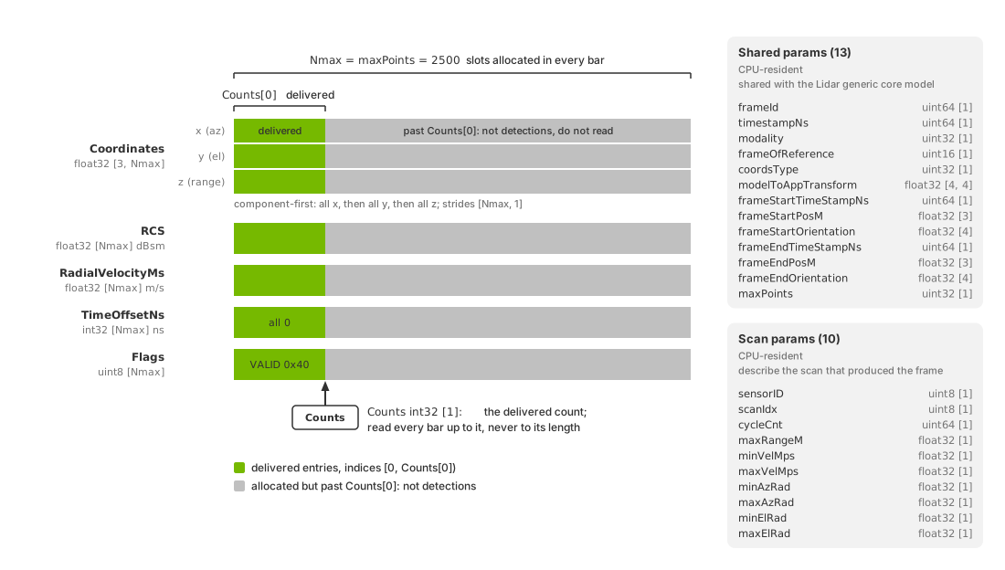
Anatomy of one radar PointCloud output. The per-detection tensors,
Coordinates as three component-first rows and RCS,
RadialVelocityMs, TimeOffsetNs and Flags as one row each, are
allocated for Nmax entries, the maxPoints capacity, and
Counts[0] marks how many of them this frame delivered. Beside the
tensors sit the CPU params: the thirteen shared with the Lidar generic core
model and the ten that describe the scan.#
Param |
Type |
Shape |
Value |
|---|---|---|---|
|
|
|
A number the process assigns to each radar model instance as it is
created, |
|
|
|
Index of the scan configuration this frame used: the position of its
instance name in the model’s scan order, counted from |
|
|
|
How many times this scan has fired, counted from |
|
|
|
The scan’s maximum unambiguous range, in meters: its |
|
|
|
The lower velocity ambiguity bound, in meters per second. In |
|
|
|
The upper velocity ambiguity bound for this frame, in meters per
second: the active |
|
|
|
The negative of |
|
|
|
The scan’s azimuth half-angle, its |
|
|
|
The negative of |
|
|
|
The scan’s elevation half-angle, its |
Compare the output’s scan-limit parameters with the authored values to check
the active configuration, including when Counts[0] is zero;
configuration verification describes
the check. USD Attributes defines
maxRangeM, maxVelMpsSequence, the angular half-angles and elevMode.
Angular units#
Angular limits and spherical coordinates use different units:
minAzRad,maxAzRad,minElRadandmaxElRad: radians.Azimuth and elevation in spherical
Coordinates: degrees.
For example, maxAzAngDeg = 75 produces limits of approximately
minAzRad = -1.309 and maxAzRad = 1.309. A detection at the positive
azimuth limit has a spherical azimuth near 75 degrees.
Convert the angles to the same units before comparing them. Compare directly
only when frameOfReference = 0 (sensor frame): the limits are always
sensor-relative, while world or custom coordinates use their selected frame.
Reading the output#
Use the RenderVar’s full prim path to locate its output:
/World/Render/Vars/PointCloud in the examples. Follow the shared
mapping,
synchronization and
lifetime rules.
The read routines of the two radar examples show the radar reading rule. The
Python one maps the output to the CPU, bounds every tensor by Counts[0],
keeps the entries whose VALID bit is set and transposes the
component-first Coordinates into one row per detection; the C one applies
the same bound and filter to RCS and RadialVelocityMs and prints the
minimum and maximum of each.
def read_radar_pointcloud(frame) -> tuple[np.ndarray, np.ndarray]:
    """Map the PointCloud composite tensor to CPU and return valid detections."""
    with frame.render_vars[POINTCLOUD_RENDER_VAR].map(device=ovrtx.Device.CPU) as pointcloud:
        coordinates = np.from_dlpack(pointcloud["Coordinates"])
        counts = np.from_dlpack(pointcloud["Counts"])
        flags = np.from_dlpack(pointcloud["Flags"])
        radial_velocity = np.from_dlpack(pointcloud["RadialVelocityMs"])

        # Counts bounds delivered entries; Flags determines per-entry validity.
        detection_count = int(counts[0])
        valid = (np.asarray(flags[:detection_count]) & 0x40) != 0
        points = np.asarray(coordinates[:, :detection_count].T)[valid]
        return (
            points.copy(),
            np.asarray(radial_velocity[:detection_count])[valid].copy(),
        )
// Read the mapped PointCloud tensors for one step. Counts bounds the delivered
// detection entries; Flags determines per-entry validity.
bool print_pointcloud_step(ovrtx_render_var_output_t const& output,
                           int step,
                           int* moving_detection_count,
                           float* max_abs_radial_velocity)
{
    // The USD requests the payload channels; the model auto-enables Counts and
    // Flags.
    int32_t const* counts_data = cpu_tensor_data<int32_t>(output, "Counts");
    uint8_t const* flags_data = cpu_tensor_data<uint8_t>(output, "Flags");
    float const* rcs_data = cpu_tensor_data<float>(output, "RCS");
    float const* radial_velocity_data =
        cpu_tensor_data<float>(output, "RadialVelocityMs");

    if (!counts_data || !flags_data || !rcs_data || !radial_velocity_data) {
        return false;
    }

    // Counts is a scalar tensor containing the delivered detection count.
    int32_t const detection_count = counts_data[0];
    if (detection_count <= 0) {
        std::cerr << "Expected at least one radar detection, got "
                  << detection_count << "\n";
        return false;
    }

    const size_t detection_entries = static_cast<size_t>(detection_count);
    constexpr uint8_t kValidFlag = 0x40;
    size_t valid_detection_count = 0;
    for (size_t i = 0; i < detection_entries; ++i) {
        if ((flags_data[i] & kValidFlag) != 0) {
            ++valid_detection_count;
        }
    }
    if (valid_detection_count == 0) {
        std::cerr << "Radar PointCloud contained no valid detections\n";
        return false;
    }

    // RCS is the radar cross section channel returned for each detection.
    bool found_finite_rcs = false;
    float min_rcs = std::numeric_limits<float>::infinity();
    float max_rcs = -std::numeric_limits<float>::infinity();

    // RCS values are regular float channel entries in the composite output.
    for (size_t i = 0; i < detection_entries; ++i) {
        if ((flags_data[i] & kValidFlag) == 0) {
            continue;
        }
        const float rcs_value = rcs_data[i];
        if (std::isfinite(rcs_value)) {
            found_finite_rcs = true;
            min_rcs = std::min(min_rcs, rcs_value);
            max_rcs = std::max(max_rcs, rcs_value);
        }
    }
    if (!found_finite_rcs) {
        std::cerr
            << "RCS tensor was present but contained no finite values for valid detections\n";
        return false;
    }

    bool found_finite_radial_velocity = false;
    float min_radial_velocity = std::numeric_limits<float>::infinity();
    float max_radial_velocity = -std::numeric_limits<float>::infinity();
    int step_moving_detection_count = 0;

    // Approaching objects report negative radial velocity; track magnitude when
    // reporting detections from the moving cube.
    for (size_t i = 0; i < detection_entries; ++i) {
        if ((flags_data[i] & kValidFlag) == 0) {
            continue;
        }
        const float radial_velocity = radial_velocity_data[i];
        if (!std::isfinite(radial_velocity)) {
            continue;
        }
        found_finite_radial_velocity = true;
        min_radial_velocity = std::min(min_radial_velocity, radial_velocity);
        max_radial_velocity = std::max(max_radial_velocity, radial_velocity);
        const float abs_radial_velocity = std::abs(radial_velocity);
        *max_abs_radial_velocity =
            std::max(*max_abs_radial_velocity, abs_radial_velocity);
        if (abs_radial_velocity > kMovingRadialVelocityThresholdMs) {
            ++step_moving_detection_count;
        }
    }
    if (!found_finite_radial_velocity) {
        std::cerr
            << "RadialVelocityMs tensor contained no finite values for valid detections\n";
        return false;
    }

    *moving_detection_count += step_moving_detection_count;

    std::cout << "  step " << step
              << ": valid points=" << valid_detection_count
              << ", RCS min/max=[" << min_rcs << ", " << max_rcs << "]"
              << ", radial velocity min/max=[" << min_radial_velocity << ", "
              << max_radial_velocity << "]"
              << " m/s\n";

    return true;
}
Read coordsType and frameOfReference before interpreting coordinates.
Counts[0] = 0 identifies a scan with no detections (Counts, Flags and the detection cap).
Using the detections#
Apply the Counts bound and the VALID filter before anything else.
Then plot Cartesian Coordinates directly as x, y, z points; for spherical
Coordinates, convert azimuth, elevation and range to Cartesian coordinates
first, or use a visualization that understands the spherical representation,
remembering that the angles are in degrees.
Coloring by signed RadialVelocityMs is a useful default: blue for
approaching detections, green near zero and red for receding ones, so that a
target closing on the sensor stands out from the static scene. The Python
example maps the signed value to such a color:
def radial_velocity_colors(radial_velocity: np.ndarray) -> np.ndarray:
    """Map signed radial velocity to RGB: blue approaching, green near zero, red receding."""
    max_abs = max(float(np.max(np.abs(radial_velocity))), 1.0e-6)
    normalized = np.clip(radial_velocity / max_abs, -1.0, 1.0)

    colors = np.empty((len(radial_velocity), 3), dtype=np.uint8)
    colors[:, 0] = np.where(normalized > 0, normalized * 255, 0).astype(np.uint8)
    colors[:, 1] = ((1.0 - np.abs(normalized)) * 180).astype(np.uint8)
    colors[:, 2] = np.where(normalized < 0, -normalized * 255, 0).astype(np.uint8)
    return colors
Color by RCS when inspecting material response or detectability. Compare
its minimum and maximum across a frame; both the scan calibration and scene
affect these values. The Python radar example shows the Counts bound, the
Flags filter and velocity coloring in a live viewer; the C radar
example requests RCS as well and
prints both ranges on every step.
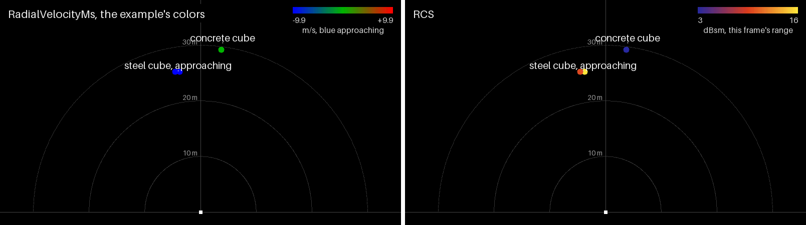
The detections of the radar example scene on step 5 of the example’s run,
seen from above, the steel cube approaching at 10 m/s and the concrete
cube standing still: left, colored by signed RadialVelocityMs with the
example’s mapping, the approaching cube blue and the static one green;
right, the same detections colored by RCS from this frame’s minimum to
its maximum. The scene is the C example’s copy, which requests RCS.#