

Set Up a Radar Sensor#
The Radar generic wpmDmat model produces detections with position, radial
velocity and radar cross section. A scene needs an OmniRadar prim with
OmniSensorGenericRadarWpmDmatAPI and a RenderProduct requesting
PointCloud. This procedure configures a radar viewing a moving cube and
a field of panels, then reads the detections.
The example ships two scenes. Its default, radar_example.usda, holds a
moving steel cube and a static concrete cube and is described on
Python: Radar Sensor. This
page builds the alternative, radar_example_field.usda, selected with
--scene radar_example_field.usda: the same moving cube crossing a field of
33 thin steel panels, scanned by a radar whose single scan is laid out
explicitly, bins and limits included, rather than left at the schema defaults.
Before you start. See Radar generic wpmDmat model for the simulation model and Outputs for channel definitions. If this is your first sensor scene, start with Your First Lidar Sensor.
Run the Python radar example with the panel-field scene:
cd examples/python/radar
uv run main.py --scene radar_example_field.usda
The C radar example drives the same scene when you pass the file’s path as its first argument. Both examples ship an identical copy of the file, and the USDA snippets below are taken from the Python example’s copy.
Request the PointCloud output#
A RenderProduct whose camera relationship targets the sensor prim renders
through it, and the RenderVars in its orderedVars say what it delivers
(refer to RenderProduct and
RenderVar). This model has one output
to request, a RenderVar with sourceName PointCloud, and the RenderVar’s
channels attribute lists the per-detection tensors the frame should carry:
radar_example_field.usda, from the runnable Python radar example##usda 1.0
def "Render"
{
def "Products"
{
def RenderProduct "RadarProduct"
{
rel camera = </World/Radar>
rel orderedVars = [<../../Vars/PointCloud>]
}
def RenderProduct "CameraProduct"
{
rel camera = </World/PreviewCamera>
int2 resolution = (960, 540)
token omni:rtx:rendermode = "RealTimePathTracing"
rel orderedVars = [<../../Vars/LdrColor>]
}
}
def "Vars"
{
def RenderVar "PointCloud"
{
uniform string sourceName = "PointCloud"
token[] channels = [
"Coordinates",
"Counts",
"RCS",
"RadialVelocityMs"
]
}
def RenderVar "LdrColor"
{
uniform string sourceName = "LdrColor"
}
}
}
from pxr import Gf, Sdf

world = stage.DefinePrim("/World", "Xform")

render = stage.DefinePrim("/World/Render", "")

products = stage.DefinePrim("/World/Render/Products", "")

radar_product = stage.DefinePrim("/World/Render/Products/RadarProduct", "RenderProduct")
radar_product.CreateRelationship("camera", custom=False).SetTargets(["/World/Radar"])
radar_product.CreateRelationship("orderedVars", custom=False).SetTargets(
    ["/World/Render/Vars/PointCloud"]
)

camera_product = stage.DefinePrim("/World/Render/Products/CameraProduct", "RenderProduct")
camera_product.CreateRelationship("camera", custom=False).SetTargets(["/World/PreviewCamera"])
camera_product.CreateAttribute("resolution", Sdf.ValueTypeNames.Int2, custom=False).Set(
    Gf.Vec2i(960, 540)
)
camera_product.GetAttribute("resolution").SetVariability(Sdf.VariabilityVarying)
camera_product.CreateAttribute(
    "omni:rtx:rendermode", Sdf.ValueTypeNames.Token, custom=False
).Set("RealTimePathTracing")
camera_product.CreateRelationship("orderedVars", custom=False).SetTargets(
    ["/World/Render/Vars/LdrColor"]
)

vars = stage.DefinePrim("/World/Render/Vars", "")

point_cloud = stage.DefinePrim("/World/Render/Vars/PointCloud", "RenderVar")
point_cloud.CreateAttribute(
    "sourceName", Sdf.ValueTypeNames.String, custom=False, variability=Sdf.VariabilityUniform
).Set("PointCloud")
point_cloud.CreateAttribute("channels", Sdf.ValueTypeNames.TokenArray, custom=False).Set(
    ["Coordinates", "Counts", "RCS", "RadialVelocityMs"]
)

ldr_color = stage.DefinePrim("/World/Render/Vars/LdrColor", "RenderVar")
ldr_color.CreateAttribute(
    "sourceName", Sdf.ValueTypeNames.String, custom=False, variability=Sdf.VariabilityUniform
).Set("LdrColor")
The scene requests RCS as well as RadialVelocityMs, so every detection
arrives with its radar cross section beside its radial velocity, and the
figures under Verification
color the detections by each in turn. Counts and Flags arrive whether or
not you list them.
Requesting the output on
Outputs names every channel you can list, and its
channel table says what each
one holds.
The second product in the same Render scope, CameraProduct, is not a
sensor output. It renders through the scene’s PreviewCamera and requests
LdrColor: the camera view of the field, there so that the scene can be
looked at, and the example never steps it. The camera animation under
Verification
was rendered through it.
Label the surfaces#
The non-visual sensors use the non-visual material labels
(omni:simready:nonvisual:*) on the Material prim bound to a surface for
calculating their responses, not the surface shader. The scene has two
materials, labeled asphalt for the ground plane and steel for the panels
and the moving cube:
The complete material definitions are in
radar_example_field.usda.
Each Material prim also carries a visual shader, so one prim serves the
radar and the preview camera; Non-Visual Sensor Materials explains the
label vocabulary, where the labels live and how a material that also drives
visual rendering keeps its shader beside them.
Place the targets#
The targets are what the scan above is laid out for. Thirty-three thin steel
panels, 2 m tall, a quarter of a meter thick and wider the farther out they
stand, are spread across the field of view from about 10 m out to nearly the
90 m maximum range, each turned to face the radar with its front face centered
in a range bin of its own, so that no two panels share a range bin; their
angular footprints do not overlap either. The moving steel cube of the default
scene crosses the field with its transform time-sampled from (30, 4, 0.75)
at time code 0 to (20, 4, 0.75) at time code 10, one meter closer to the
radar per 0.1 s step, a closing speed of 10 m/s.
The complete target layout are in
radar_example_field.usda.
Create the renderer with the motion BVH enabled#
This model needs an active motion BVH for motion effects, with AUTO or
ENABLE. Create the renderer with ENABLE, as the example does. The Python
snippet also creates the stage the scene is loaded into and attaches it to the
renderer:
main.py, from the runnable Python radar example## Create the renderer. Radar defaults are provided by the ovrtx runtime.
# Enable motion BVH: required for moving-object radial velocity in the radar pipeline.
log_file_path = None
if args.log is not None:
args.log.parent.mkdir(parents=True, exist_ok=True)
log_file_path = str(args.log)
renderer = ovrtx.Renderer(ovrtx.RendererConfig(
log_file_path=log_file_path,
motion_bvh=ovrtx.MotionBvh.ENABLE))
stage = ovstage.Stage("ovrtx.example.radar")
renderer.attach_ovstage(stage)
main.cpp, from the runnable C radar example#// The STATIC ovrtx loader resolves the ${executable_dir} token to the running
// executable's directory; ovrtx_setup_runtime() links the package bin beside
// the exe as "ovrtx/", which we hand the loader as the binary package root.
ovx_string_t ovrtx_package_root = {
OVX_CONFIG_EXECUTABLE_DIR_TOKEN "/ovrtx",
sizeof(OVX_CONFIG_EXECUTABLE_DIR_TOKEN "/ovrtx") - 1};
// Enable motion BVH: required for moving-object radial velocity in the radar
// pipeline.
ovrtx_config_entry_t config_entries[] = {
ovrtx_config_entry_binary_package_root_path(ovrtx_package_root),
ovrtx_config_entry_motion_bvh(OVRTX_MOTION_BVH_ENABLE),
};
ovrtx_config_t config = { config_entries, 2 };
// Create the renderer before attaching a stage or populating the scene.
result = ovrtx_create_renderer(&config, &renderer);
if (!check_api_result(result, "create_renderer")) {
return 1;
}
Motion BVH describes the switch in full: the modes, the C call, its lifetime and GPU support. Motion BVH states the requirement for this model, and the motion BVH on Simulate Moving Targets says what the radar does without it.
Load the scene and warm up#
Open the USDA named by --scene into the attached stage and wait until that
write has landed, so the sensor and its product exist before the first step:
# The USDA scene defines the radar, materials, render product, and animated cube.
print(f"Loading radar scene from {args.scene}...")
ordinal = 1
ovstage.population.open_usd(stage, str(args.scene), ordinal=ordinal)
stage.advance_write_floor(ordinal, ovstage.Scope.ALL).wait()
// Initialize the STATIC ovstage loader with its package root, mirroring the
// ovrtx setup above. ovstage_setup_runtime() links the package bin beside the
// exe as "ovstage/" (next to "ovrtx/"). ovrtx_create_renderer() already loaded
// the shared usd_ms runtime; ovstage.dll loads lazily on the first ovstage
// call and reuses it.
ovx_string_t ovstage_package_root = {
    OVX_CONFIG_EXECUTABLE_DIR_TOKEN "/ovstage",
    sizeof(OVX_CONFIG_EXECUTABLE_DIR_TOKEN "/ovstage") - 1};
ovstage_config_entry_t stage_config_entries[] = {
    ovstage_config_entry_binary_package_root_path(ovstage_package_root),
};
ovstage_config_t stage_config {};
stage_config.entries = stage_config_entries;
stage_config.entry_count =
    sizeof(stage_config_entries) / sizeof(stage_config_entries[0]);
ovstage_api_status_t stage_init_status = ovstage_initialize(&stage_config);
if (stage_init_status != OVSTAGE_OK) {
    print_ovstage_error(nullptr, stage_init_status, "initialize");
    return cleanup(1);
}

// Create the ovstage instance and attach it to the renderer.
ovstage_instance_desc_t stage_desc {};
stage_desc.name = "radar";
ovstage_api_status_t stage_result = ovstage_create_instance(&stage_desc, &stage);
if (stage_result != OVSTAGE_OK) {
    print_ovstage_error(stage, stage_result, "create_instance");
    return cleanup(1);
}

result = ovrtx_attach_ovstage(renderer, stage);
if (!check_api_result(result, "attach_ovstage")) {
    return cleanup(1);
}
stage_attached = true;

// Populate the stage from the local USD file at time 0 and our starting
// ordinal, then commit the write floor so the attached renderer can see it.
std::cout << "Loading radar scene from " << sceneFilePath << "...\n";
ovstage_population_enqueue_result_t populate_result =
    ovstage_population_open_usd_from_file(stage,
                                          to_ovx_string(sceneFilePath),
                                          stage_ordinal,
                                          /* time = */ 0.0,
                                          OVSTAGE_POPULATION_DOMAIN_RENDERING);
if (wait_population_op(stage, populate_result, "population_open_usd_from_file") ||
    commit_ovstage_ordinal(stage, stage_ordinal)) {
    return cleanup(1);
}
Warm the renderer up before you read a frame. The example places the scene’s animation at time zero and takes three steps there before the animated loop begins; each step renders the radar product and advances the simulation by 0.1 s, one scan period at the authored 10 Hz, so that every step fires one scan:
# Warm up the sensor before reading the animated frames. Each USD-time
# update is a stage mutation, published under its own ordinal.
ordinal += 1
ovstage.population.update_from_usd_time(stage, ordinal, 0.0)
stage.advance_write_floor(ordinal, ovstage.Scope.ALL).wait()
for _ in range(WARMUP_STEPS):
    renderer.step(render_products={RENDER_PRODUCT}, delta_time=STEP_DT_SECONDS, ordinal=ordinal)
// The initial population already sampled time 0, so render a few warmup
// frames from that committed ordinal without reading outputs. In attach mode
// we drive the renderer with ovrtx_step_with_stage().
for (int i = 0; i < kWarmupStepCount; ++i) {
    ovrtx_step_result_handle_t warmup_handle{};

    // Warmup frames let the sensor pipeline settle before reading the
    // first PointCloud.
    enqueue_result =
        ovrtx_step_with_stage(renderer,
                              render_products,
                              kStepDeltaTimeSeconds,
                              stage_ordinal,
                              &warmup_handle);
    if (!check_api_result(enqueue_result, "step") ||
        !wait_for_success(renderer, enqueue_result.op_index, "step")) {
        destroy_step_results(renderer, &warmup_handle);
        return cleanup(1);
    }
    if (!destroy_step_results(renderer, &warmup_handle)) {
        return cleanup(1);
    }
}
Note
Warming up the renderer counts the sensor pipeline among the reasons to warm the renderer up, beside texture streaming and path-tracing convergence. Why the step length matters is on the radar frame rate and, for every sensor, on Sensor Scheduling.
Step the scene and read the detections#
The Python and C examples step by 0.1 s and print the valid-entry count and radial-velocity range for each frame.
To read detections, map PointCloud to CPU memory, limit reads to
Counts[0] and filter by the VALID bit. Convert the component-first
Coordinates layout to one row per detection if needed. See the paired
reading examples and
sensor-output mapping, synchronization and lifetime rules.
Verification#
Run the example with the panel-field scene and expect one printed line per
step. In the recorded run shown below, frames contained 35–37 valid points.
The minimum radial velocity was near −9.9 m/s for the approaching cube;
the maximum was near zero for the stationary panels. Its first line was
step 1: valid points=35, radial velocity min/max=[-9.921682357788086, 0.0003972465347032994] m/s.
These are example observations, not required counts or exact results for
other runs.
Expect negative radial velocity from the approaching cube. Its motion is the same in both example scenes; see Doppler measurements for the derivation. The expected velocity is within the ±16.33 m/s interval configured by the scan’s one-entry velocity sequence.
|
|
|
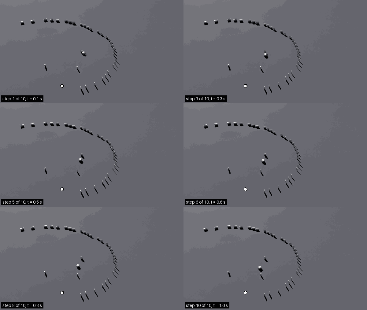
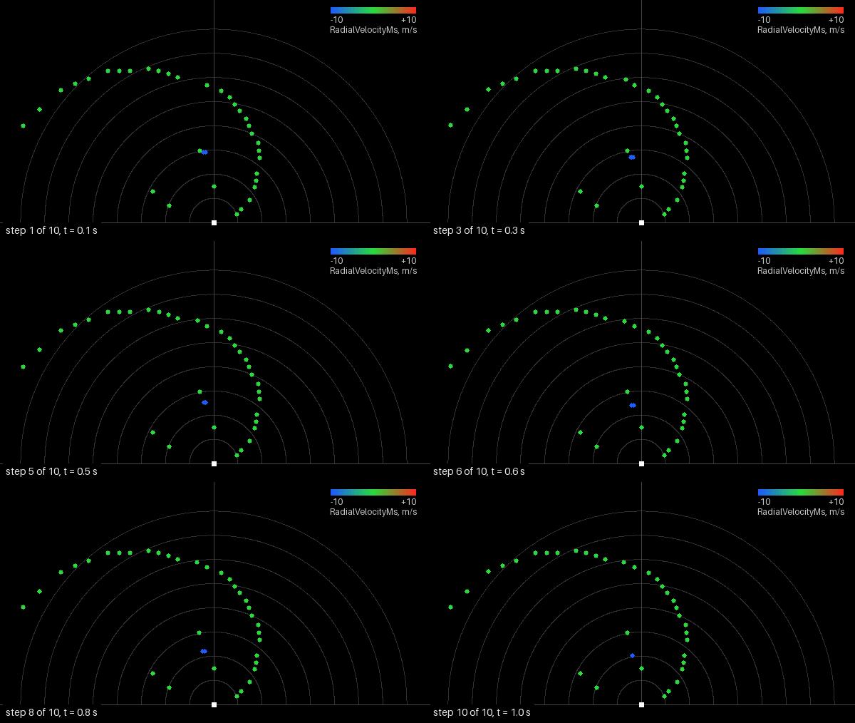
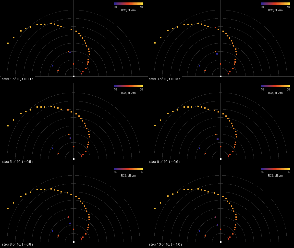
The scene over the ten steps, three views of the same frames. Left, the camera
view through PreviewCamera, the radar marked white: the moving cube
crossing the field of panels.
Center, a top view of each step’s detections with the radar at the bottom edge
looking up the image and 10 m range rings, colored by RadialVelocityMs on a
±10 m/s scale, blue closing, green still, red receding: the cube’s detection
comes out blue, the panels’ green. Right, the same detections colored by
RCS on a fixed 15 to 55 dBsm scale. The three animations are
frame-synchronous and carry the step number and time in their corner.
The example’s Rerun viewer also colors detections by signed radial velocity. Use the enabled/disabled comparison on this scene to check that motion BVH affects target velocity.
A scan that detects no targets is still published with Counts[0] = 0
and scan metadata; the example prints valid points=0. A step without a
radar firing returns no radar PointCloud frame. See empty scans.
Potential issues#
The viewer shows two targets instead of the panel field: check which scene was loaded. The example prints the scene it opens (
Loading radar scene from ...); pass--scene radar_example_field.usdafrom the example’s directory, or the file’s full path from anywhere else.Some steps return no radar frame: the steps may be shorter than the radar’s scan period, so only a step that contains one of the radar’s acquisition times fires a scan. Step the product at the scan period, as the example does (Step at the scan period).
Detections arrive, but the moving cube’s radial velocity stays near zero, so the printed minimum sits near zero instead of near -10 m/s: the renderer was created without the motion BVH, or on a GPU that cannot trace against motion. The model needs the motion BVH says what the radar does without it, and Motion BVH how to set it and which GPUs support it.
The cloud looks plausible but lies in the wrong place, or carries angles where you expected meters: the coordinate system or the frame of reference is not the one you assumed. Read the
coordsTypeandframeOfReferenceparams of the frame first (Reading the output) and check the three attributes of the output group.Published frames print
valid points=0: the acquisitions produced no valid detections. Check the target’s position, range, materials and detection thresholds per Validate a Parameterization. An empty scan has a delivered count of zero; tensor capacity does not imply that detections are present.The labels seem to make no difference: an attribute of the wrong type or a misspelled token keeps a label from being read. Non-Visual Sensor Materials describes label authoring; Symptom Index lists the checks to make, in order.