

Outputs#
The Camera single-view stereo depth model post-processes renderer outputs and
publishes five image tensors at the RenderProduct’s resolution, with
channel-last shapes. Request them as RenderVars on the product that renders
through the model’s Camera.
See Set Up a Depth Product for the required input and output requests, and Sensor Outputs for mapping and reading tensors. The sections below define the formats, units, coordinate frames and invalid values.
Inputs#
The post-processing pipeline reads three renderer outputs from the same RenderProduct and produces five sensor outputs. The camera output tables define the inputs and their units. The model uses them as follows:
DistanceToImagePlaneSD supplies the rendered distance, in meters, that the model processes.
Camera3dPositionSD supplies the point positions, in scene units. The model copies them into its point cloud; it does not reconstruct positions from the distance.
LdrColor supplies the luminance the confidence test works on and the color associated with each point. It is the tone-mapped 8-bit sRGB image with alpha, values 0 to 255.
Two other camera outputs report distance and are not read here: DistanceToCameraSD and DepthSD; the camera output tables define and compare the three.
The model places no condition on the render mode. It runs on every product that delivers the three inputs; the camera output tables say which render modes deliver each of them.
DepthSensorDistance is the model’s processed distance output, in meters.
A zero denotes an invalid measurement. Reconstructed depth data describes the modeled
stereo-camera effects.
The model is independent of the Camera generic core model, which runs on a camera of its own, since a camera
carries one sensor model, and reads HdrColor rather than LdrColor;
the overview says how the two relate.
The required set#
Requesting any of the five DepthSensor* outputs enables the depth
post-processing pipeline on that RenderProduct. The pipeline runs after the
renderer produces the frame. Applying OmniSensorGenericDepthSensorSingleViewAPI
to the product’s camera sets the parameters; the pipeline runs only when its
outputs are requested.
The product must request three inputs and at least one depth output:
Request
LdrColor,DistanceToImagePlaneSDandCamera3dPositionSD. If an input is missing, an error is logged and no depth output is written.Request whichever outputs you need:
DepthSensorImager,DepthSensorDistance,DepthSensorPointCloudPosition,DepthSensorPointCloudColororDepthSensorOutputVisualization. Any one of these enables the pipeline; requesting all five is optional.
The RenderVar prims that request these eight names and the orderedVars
relationship that lists them are shown in Set Up a Depth Product
and explained in Output Configuration.
Post-processing stages#
The model post-processes each rendered frame once per product in six stages. Several stages can invalidate measurements. Check them in order when a depth value is missing.
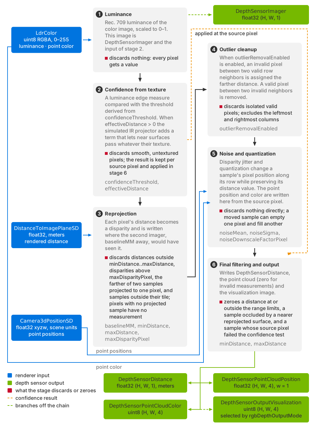
The six post-processing stages read LdrColor,
DistanceToImagePlaneSD and Camera3dPositionSD and produce the five
sensor outputs. Labels identify the measurements each stage discards.
DepthSensorImager is produced by stage 1 and
DepthSensorOutputVisualization by stage 6.#
Luminance. The tone-mapped color image is reduced to one luminance value per pixel with the Rec. 709 weights and normalized to the 0–1 range. That image is
DepthSensorImager, and it is also the input of the next stage. Nothing is discarded here: every pixel gets a value.Confidence, from image texture. Each pixel of the luminance image is tested for texture against the threshold derived from
confidenceThreshold, with a simulated IR projector contribution withineffectiveDistance(the confidence attributes define the calculation). Smooth, untextured regions fail, simulating a stereo matcher’s failure to find correspondences there. The result is recorded per pixel of the rendered view and applied in the last stage.Reprojection. Each pixel’s rendered distance is converted to a disparity and written into the pixel that the second imager, displaced by
baselineMM, would have seen it in (the optics attributes define the disparity and give the relation). A distance outside the range limits,minDistancetomaxDistance, or a disparity abovemaxDisparityPixel, is dropped before it is written. The maximum disparity determines the near limit of reprojection. When two surfaces project to the same destination pixel, the nearer sample is retained. Pixels with no projected sample have no measurement. These occlusion holes correspond to regions hidden from one of the two viewpoints, and they widen as the baseline grows. On a tiled product, one whoserel cameralists several cameras each rendered into its own tile of the frame (Set Up a Depth Product), a sample must project within its own camera’s tile; samples that project into a neighboring tile are discarded.Outlier cleanup, when
outlierRemovalEnabledis on, which it is by default: the single-pixel row cleanup that the confidence attributes describe fills an invalid pixel between valid neighbors and removes a valid pixel between invalid neighbors. It skips the leftmost and rightmost columns.Noise and quantization, applied to the disparity: a sample moves along its row, so this stage can empty one pixel and fill another (the noise attributes say how the jitter and the step are drawn; Tune Noise, Quantization and Confidence says how much to add and how to turn it off). The point cloud entry and its color are written here too, taken from the pixel of the rendered view the sample came from.
Final filtering and output. A distance at or outside the range limits is zeroed, a sample that a nearer reprojected surface should have occluded is zeroed, and a sample whose source pixel failed the confidence test is zeroed. Accepted distances are written to
DepthSensorDistance; the point cloud entry is zero for invalid measurements, and the visualization image is written in the same stage.
What comes back#
The table lists the five outputs and their invalid measurement values. Types
have explicit widths: float32 is a 32-bit floating-point type and uint8
is an 8-bit unsigned integer type.
|
Type |
Shape |
Description |
|---|---|---|---|
|
float32 |
|
The simulated distance, in meters. Zero means no measurement. |
|
float32 |
|
Position of each point in the rendered camera’s frame, in scene units,
with |
|
uint8 |
|
The color of the source pixel for each point, as RGBA. An entry with no measurement is opaque black. |
|
float32 |
|
Luminance of the rendered view, 0–1. Written for every pixel, whether or not the depth sample was accepted. Also the confidence stage’s input, which is why it must be requested. |
|
uint8 |
|
The diagnostic image selected by |
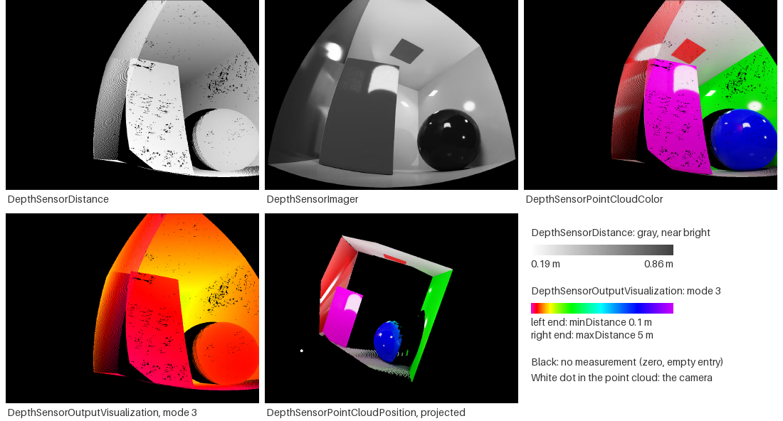
The five outputs of a Cornell box test scene’s fisheye depth product, from
one frame. DepthSensorDistance as a grayscale image, near bright, zero
black; DepthSensorImager, the luminance of the rendered view from 0 to
1; DepthSensorPointCloudColor, the color associated with each point, empty
entries opaque black; DepthSensorOutputVisualization in mode 3; and
DepthSensorPointCloudPosition projected from a viewpoint beside and
above the camera, each point in the color of DepthSensorPointCloudColor
and the white dot marking the camera. Outside the lens’s image area and
wherever the model produced nothing, every output holds its no-measurement
value.#
Invalid measurements#
Zero denotes an invalid measurement. Occlusion holes, failed confidence,
distances outside the range limits and disparities above the maximum all
resolve to the same zero distance and the same all-zero point. There is no
separate validity channel, so a consumer filters on the distance being non-zero,
or on the point’s w component. Large empty regions are the normal behavior
of this model on an untextured scene, not a failure.
Note
Reading the outputs after too few rendered frames leaves speckled dropouts across the depth image: where the color has not yet resolved, there is no texture for the confidence test to pass. Warm the renderer up before you judge coverage (Output Configuration).
Two frames#
The distance image and the point cloud share a pixel grid but not a frame. Both
are images at the product’s resolution, laid out row by row, so the entry for
row r and column c of either array is at index r × width + c of its
flat tensor. That grid is the second imager’s, because that is where
reprojection put each sample. The point and its color at (r, c) belong to
the distance at (r, c). Positions are read from Camera3dPositionSD at
the source pixel, one noisy disparity to the side in the same row.
Camera3dPositionSD holds the camera-space positions of the rendered view,
so the points are in the rendered camera’s own frame. A consumer that projects
the point cloud with the depth image’s geometry, or vice versa, is mixing two
frames.
Units#
Distances are in meters; point positions are in scene units. The renderer
delivers DistanceToImagePlaneSD in meters whatever the stage’s
metersPerUnit (the camera output tables are
canonical for the input units), and this model applies no unit conversion of its
own. So DepthSensorDistance, the minDistance and maxDistance limits
and the effectiveDistance range are meters on every stage.
DepthSensorPointCloudPosition is taken from Camera3dPositionSD, which is
in scene units, so on a stage whose metersPerUnit is not 1 the point cloud
is not in the unit of the distance image.
Visualization#
rgbDepthOutputMode selects one image, written to the dedicated
DepthSensorOutputVisualization output. It does not modify LdrColor.
Values outside the table fall back to mode 0.
Value |
Image |
|---|---|
|
The rendered color, passed through. The default. |
|
Grayscale ramp that repeats every meter of distance. |
|
Grayscale gradient across |
|
Rainbow gradient across the same interval, shifted so that near values are purple; pixels with no measurement are black. |
|
The depth of the position input ( |
|
The reprojected distance, before noise and confidence culling. |
|
The confidence map: pixels that passed the threshold at full brightness, the rest showing the raw texture gradient. |
|
The disparity computed from that input depth, in grayscale. |
Every mode but 0 and 6 quantizes a distance or disparity to an 8-bit value, so
they are diagnostic images and not measurements; read DepthSensorDistance
for a number. showDistance marks the center pixel of the visualization for
a quick check against a target at a known distance (the visualization
attributes describe the
readout).
Note
Modes 2 and 3 normalize their gradient between minDistance and
maxDistance, so author a realistic maxDistance before using either;
the range limits
explain why the default leaves both images effectively uniform.
Attributes that shape the output#
Every attribute of OmniSensorGenericDepthSensorSingleViewAPI is explained, with its
unit, clamps and relations, on USD Attributes; types and
defaults are in the generated Sensor API Schemas.
Grouped by what they do to the outputs:
Optics set how much disparity a distance produces and, through the maximum disparity, the closest distance the sensor can see:
baselineMM,focalLengthPixel,sensorSizePixelandmaxDisparityPixel. The product’s width enters the disparity too, so changing the resolution moves the near limit (Build a Profile from a Spec Sheet).Range limits bound the accepted distance interval and the visualization interval:
minDistanceandmaxDistance.Noise changes sample pixel positions through disparity jitter and quantization:
noiseMean,noiseSigmaandnoiseDownscaleFactorPixel.Confidence decides where depth exists at all:
confidenceThreshold,effectiveDistanceandoutlierRemovalEnabled.Visualization selects the diagnostic image and the center-pixel readout:
rgbDepthOutputModeandshowDistance.