

USD Attributes#
The Camera generic core model is instantiated by applying
OmniSensorGenericCameraCoreAPI to a Camera prim. Unlike the non-visual
models, it has no sensor prim type of its own: the schema can only be applied to
a Camera, so the sensor is the camera you already render through, and the
camera’s own intrinsics (focal length, aperture, clipping range) keep governing
the rendered view exactly as before. Those intrinsics are the UsdGeomCamera
attributes of USD Camera Attributes; what
the model does and does not read of the camera is on the Overview.
This page explains what the model’s own attributes mean: their units, the order
in which they act within a stage, and how they relate to one another. They are
grouped as the model groups them: color correction, color filter array, sensor
noise, companding and ISP. Types, defaults and allowed tokens are not repeated
here; the generated OmniSensorGenericCameraCoreAPI table in Sensor
API Schemas lists every attribute with its type,
default and doc string. The Camera single-view stereo depth model publishes its
own attribute set under its own namespace; see its USD attributes.
Namespaces#
Two namespaces, and one of them is a case trap. The attributes that identify
which model to load, and schedule it, sit in plain omni:sensor:, because
every sensor model shares them; Sensor Configuration describes that shared set. Everything this
model reads is omni:sensor:core:*, with a lower-case core.
One capital-C attribute does belong on a camera, and it is not an attribute
of this model: omni:sensor:Core:partialOutputs is the camera’s
exposure-portion delivery policy, whether an exposure that spans several steps
delivers every portion or only the completed frame, and Rolling Shutter and Sensor Scheduling describe it.
This page writes leaf names under omni:sensor:core:: read
colorCorrectionBlack as omni:sensor:core:colorCorrectionBlack.
Identification and scheduling#
Applying the schema authors the shared identity attributes:
omni:sensor:modelName as "CameraCore", omni:sensor:modelVendor as
"NVIDIA" and omni:sensor:marketName as "Generic". Model
identity explains what the three decide
in general. On a Camera they are read together: the pipeline recognizes
this model by exactly the set the schema writes, so keep all three at those
values. What runs the pipeline on a product is requesting the model’s output
names on a product whose camera carries this schema, as the section on what
enables the pipeline in Outputs explains.
Three shared attributes schedule the sensor; Shared attributes on Sensor
Configuration defines them. This schema sets omni:sensor:frameRate to
(30, 1), so applying it schedules the camera at 30 Hz, however often you
step; author (0, 1) to leave the camera unscheduled and render on every
step. omni:sensor:startTime and omni:sensor:frameLimit keep the shared
defaults. Frame rate, step and delivery on Sensor Scheduling says
what the rate does to scheduling and delivery.
omni:sensor:frameRate cannot be changed on a running sensor; the schema’s own
declaration says so. It is the only attribute of this schema class that carries
such a note; Runtime Parameter Updates
covers how to tell for the others.
The attribute groups#
The sequence of operations is fixed; what you author decides how each behaves. You do not wire a graph by hand: the attributes on the camera prim configure a pipeline whose shape is already set, and Outputs gives the order of the stages and what each one publishes. The one exception is the ISP stage, which runs a program you supply rather than one assembled from attributes. The groups, by the operation they configure: color correction (black level and full-well normalization, the response scale, the 3×3 matrix and the white balance), the color filter array (the four weight triples of the 2×2 mosaic, its semantic label, its output format and the maximal value that puts codes in sensor units), sensor noise (the dark-shot parameters and the high-dynamic-range combination table), companding (the curve, its two pedestals and the code’s alignment within the output integer) and the ISP (the program, and the raw format and padding mode that describe the companded codes to it).
Two of the groups reshape the element formats in addition to changing the
pixels values: colorFilterArrayOutputDataTypeFormat changes the
element type of the color filter array tap, the companding curve decides whether
the companded image, OmniCameraSensorPreIsp, is written as 16- or 32-bit
integers. Additionally, an empty ispSmodelCameraProgram leaves the two post-ISP outputs
without an image. Outputs lists all three beside the per-stage
format table.
Color correction#
Color correction is where the rendered image is made to look like what this sensor would have measured rather than what a neutral observer would see. Real photosites do not have the spectral response of the render’s primaries, so a 3×3 matrix maps render primaries onto sensor primaries, and per-component gains account for the illuminant and for the sensor’s own digital-number scale. The stage reads the linear high-dynamic-range input (Configure the Input Image) and writes a color image of the same shape; its output format is fixed, four-component 16-bit float, as the format table on Outputs lists.
Within the stage the operations are ordered, and the first is gated:
Black level and full-well normalization, only while
colorCorrectionApplySaturationis true, which is not the default.colorCorrectionBlack, the black floor in the input’s units, is subtracted from every component and the result is floored at zero; the result is then divided bycolorCorrectionFullwellBlack, the input level at which the photosite saturates, and clamped at 1. WhilecolorCorrectionApplySaturationis false,colorCorrectionBlackandcolorCorrectionFullwellBlackhave no effect, so authoring either one alone changes nothing you can measure.Sensor response scale.
colorCorrectionSensorResponseScalemultiplies every component, so the stage’s output is linear in the authored value.The 3×3 matrix. It is authored as nine separate scalars,
colorCorrectionMatrixRrthroughcolorCorrectionMatrixBb, not as one matrix-valued attribute. The naming is output from input:colorCorrectionMatrixRgis the green input’s contribution to the output red, andRr,RgandRbtogether form output red. The identity, ones on the diagonal and zeros elsewhere, is the default and leaves color untouched.White balance.
colorCorrectionWhiteBalanceis three gains in R, G, B order, applied after the matrix. It compensates for the color temperature of the illuminant and can also scale values into the sensor’s digital-number range.
The matrix coefficients and the gains are dimensionless; the black level and the full-well level are in the units of the input image.
Three more attributes of this group, colorCorrectionRedBlueSwap,
colorCorrectionOutputFloat16 and colorCorrectionOutputFloat32, have no
effect in ovrtx: the stage writes four-component 16-bit float regardless, and
authoring them is not an error. Limitations lists them.
Attribute |
What it does |
|---|---|
|
Switches on the black level and full-well normalization step; false by default. While false, the next two attributes have no effect. |
|
Black floor subtracted from every component, in the units of the input
image; the result is floored at zero. Read only while
|
|
Input level at which the photosite saturates, in the units of the input
image; the black-subtracted value is divided by it and clamped at 1.
Read only while |
|
Dimensionless multiplier applied to every component; the stage’s output is linear in it. |
|
The nine dimensionless coefficients of the 3×3 matrix from render primaries to sensor primaries, named output from input; the identity by default. |
|
Three dimensionless gains in R, G, B order, applied after the matrix. |
|
No effect in ovrtx; the stage writes four-component 16-bit float regardless. |
Color filter array#
This is the first of the two groups that reshape the element formats.
This stage is the mosaic filtering that Why the color filter array matters on Author a Color Filter Array explains: it takes the color-corrected RGBA image and produces one sensor code per pixel, exactly as the physical mosaic over the photosites would.
The stage encodes the RGBA input into a single-component color filter array image.#
The pattern is four RGB weight triples, one per position in the 2×2 block.
colorFilterArrayCfaCf00 is the top-left position, colorFilterArrayCfaCf01
the top-right, colorFilterArrayCfaCf10 the bottom-left and
colorFilterArrayCfaCf11 the bottom-right. Each is three floats, the weights
of red, green and blue, and the code written for a pixel is the weighted sum of
the pixel’s red, green and blue, scaled by colorFilterArrayMaximalValue. A
triple of [0, 1, 0] is a green filter, [1, 0, 0] a red one, and
[1, 1, 1] is a clear pixel, no filter at all.
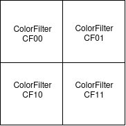
The four positions of the 2×2 block and the attribute that carries each one’s weight triple.#
Because the weights are independent, any 2×2 mosaic can be expressed. The
shipped defaults are green, red, blue, green reading across and down, a GRBG
Bayer pattern, one of the four orderings of the classic arrangement below, and
the default of the semantic token, GRBG, agrees with them.
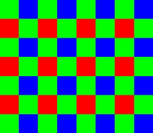
A Bayer mosaic; the shipped default GRBG is one of its four orderings.#
The semantic token names the pattern; it does not create it.
colorFilterArrayCfaSemantic records which pattern you intended, and takes
one of nine values: RGGB, GRBG, BGGR, RCCB, CRBC, BCCR,
RCCC, CCCR or CRCC. The image is produced from the four weight
triples alone, so the token is a label for whoever reads the scene, not an input
to the stage: setting it to RCCB while leaving Bayer weights in place gives
a Bayer image labeled RCCB, and the values must agree. Change the
weights and the token together, always; Author a Color Filter Array gives the triples for each pattern. An all-clear
arrangement, CCCC, all four positions clear and effectively monochrome, has
no token of its own; express it with four [1, 1, 1] triples. Why the color filter array matters
on Author a Color Filter Array explains what the
choice of mosaic trades off, low-light sensitivity against color separation.
The output format changes this stage’s element type only.
colorFilterArrayOutputDataTypeFormat is UINT32 by default or FLOAT32.
With UINT32 each code is written as an unsigned integer, rounded down; with
FLOAT32 the fractional code is kept. The noise stage converts FLOAT32
codes back to unsigned integers before it adds noise, so every later stage works
on integer codes either way and the float representation ends at
OmniCameraSensorPostCfa; the format table on Outputs shows
the consequence for each tap.
The maximal value puts the result in sensor-code units.
colorFilterArrayMaximalValue multiplies the weighted sum. If the incoming
image is normalized to 1, it is the maximal code the sensor can produce:
16777215 for a 24-bit internal range, 1048575 for 20 bits, 1 for
pass-through. If the incoming image is not normalized, it is simply a linear
multiplier; either way it is a multiplier, not a clamp. The attribute is
declared float so that a non-integer radiometric scale can be authored as
readily as a bit-depth maximum. A 32-bit float represents integers exactly only
up to 224, so the 24-bit default is held exactly and a larger integer
maximum may be rounded.
Attribute |
What it does |
|---|---|
|
The RGB weight triple of the top-left, top-right, bottom-left and bottom-right position of the 2×2 block; a pixel’s code is its red, green and blue weighted by the triple of its position, scaled by the maximal value. The defaults form a GRBG Bayer pattern. |
|
Token naming the pattern you intended, one of nine; a label for whoever reads the scene, not an input to the stage. |
|
|
|
Multiplier on the weighted sum, not a clamp; with an input normalized to
1 it is the sensor’s maximal code ( |
Sensor noise#
Two noise sources are modeled, and they have different physical causes. Photon shot noise is the randomness of photon arrival itself: it grows with the signal, so a bright pixel is noisier in absolute terms and cleaner in relative terms. Dark shot noise comes from thermally generated carriers and is present whether or not light is: it does not scale with the signal, which is why it dominates in shadows and in short exposures. Both are random from frame to frame.
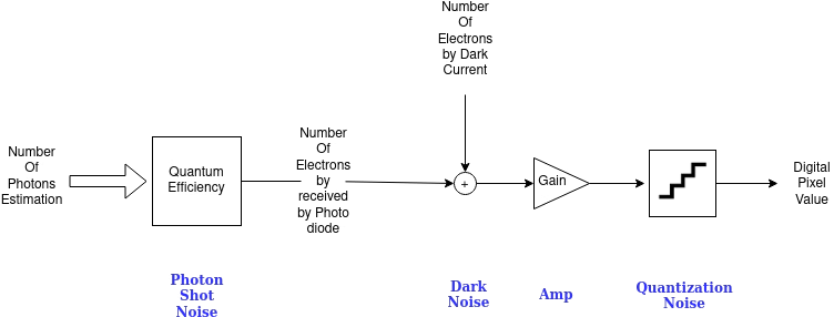
The sensor noise chain; the model implements its photon-shot and dark-shot terms.#
Only these two are modeled; spatial noise is not. Fixed-pattern noise, photo-response non-uniformity (PRNU) and dark-signal non-uniformity (DSNU) are per-photosite offsets and gains that do not change from frame to frame, the texture a real sensor imprints on every image. None of them is simulated, so fixed-pattern artifacts do not appear in this output. Limitations lists this as a limit of the model.
Two attributes control dark shot noise, and neither controls photon shot
noise. noiseDarkShotNoiseSigma is the standard deviation of the dark-shot
distribution, in sensor codes, and noiseDarkShotNoiseGain scales it; the two
multiply, so the defaults of 0.5 and 10.0 give a dark-shot term with a
standard deviation of five codes. Photon shot noise has no attribute at all,
because its magnitude follows from the signal: its standard deviation is the
square root of the pixel’s code, which is what makes it shot noise rather than
a tunable. Both terms are added to the code and the sum is floored at zero.
Because the photon term is the square root of the code, the scale you choose
with colorFilterArrayMaximalValue sets its absolute size: about 4096 codes
at the 24-bit maximum of 16777215, one code at a code of 1, and none at a code
of 0.
High-dynamic-range sensors capture in zones, and the noise model follows
them. An HDR sensor covers a wider range than one exposure can by combining
several captures taken at different gains and stitching them into one code
space. Noise is not uniform across that stitched range: a code that came from
the high-gain capture carries less real signal, and therefore more relative
noise, than the same code from the low-gain capture. noiseHdrCombinationData
describes that structure as a list of pairs, one per zone in order of increasing
code: the zone’s gain, then its upper bound in code space. For each pixel the
model takes the first zone whose bound exceeds the pixel’s code, or the last
zone when none does, divides the code by that zone’s gain to recover the
underlying signal, computes both noise terms against that, and scales the
result back by the gain. A table with one pair or none means the plain
single-exposure path. The shipped default has three zones; the generated table
in Sensor API Schemas lists it.
Attribute |
What it does |
|---|---|
|
Standard deviation of the dark-shot distribution, in sensor codes, before the gain. |
|
Dimensionless scale on that standard deviation; the product of the two is the dark-shot term’s standard deviation in codes, five with the defaults. Photon shot noise has no attribute; it follows from the code. |
|
The HDR zones as pairs of gain and upper bound in code space, in increasing code order; one pair or none means the single-exposure path. |
Companding#
This is the second of the two groups that reshape the element formats.
Companding compresses the sensor’s wide internal range onto the narrower RAW width it transmits, with a piecewise-linear curve that the ISP later reverses (compress and expand); the Overview explains why a sensor does this rather than truncate.
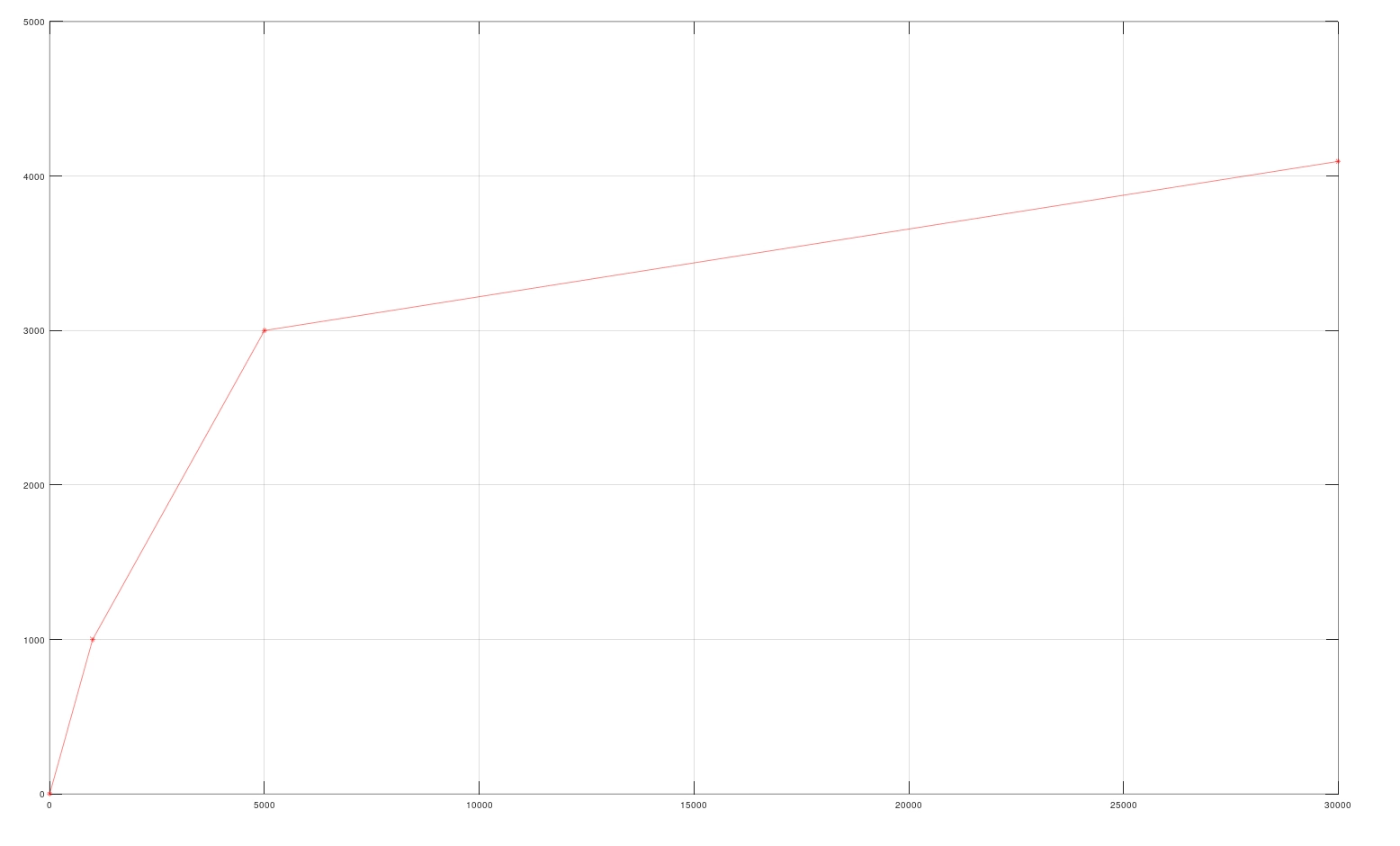
A piecewise-linear companding curve mapping a wide internal range onto RAW12.#
The curve is authored as its knee points. compandingLinearCompandCoeff
is a list of (x, y) pairs, where x is the uncompressed internal value and
y the compressed output code. Between two knees the mapping is linear; from
the last knee on, the output clamps to that knee’s y; the result is rounded to
an integer code. Author at least two pairs, in increasing x. The schema ships
a 17-point curve that maps 0 to 16777215 onto 0 to 4095, which is 24-bit
internal onto RAW12; Sensor API Schemas has it
written out, and Compand to a RAW Format and Run the ISP shows how to build a curve for another width.
A pedestal is a constant offset, and there are two of them.
compandingPrePedestal is added to the value before the curve is applied, in
internal units; compandingPostPedestal is added to the code after the curve,
in output codes, before the alignment shift. Negative values count as zero. Real
sensors carry a pedestal so that noise around black does not clip at zero and
become one-sided.
Alignment determines the code’s bit positions in the output integer.
A 12-bit code can occupy the least or most significant 12 bits of a 16-bit
unsigned integer, depending on the receiver’s requirements.
compandingAlignment specifies the position of the code’s most significant
bit in the output integer, counting from 0 at the least significant bit.
Bit positions range from 0 to 15 for a 16-bit integer and 0 to 31 for a 32-bit
integer. The stage derives the shift from that position and the number of bits
needed for the curve’s largest output. For a RAW12 curve with a maximum output
of 4095, compandingAlignment = 15 shifts the 12-bit code left by 4 into
bits 15 to 4; compandingAlignment = 11 leaves it unshifted in bits 11 to 0.
An alignment below the code width minus one shifts the code right and discards
its least significant bits. The post-pedestal is excluded from the shift
calculation, so ensure the
shifted value, including the post-pedestal, fits in the output integer.
The diagram beside Choose the alignment draws both
layouts.
The curve’s largest output determines the companding output type. The ISP requires 16-bit unsigned integer input. Stay within 16 bits states the rule and what happens to a product that requests both; Limitations records the requirement.
Attribute |
What it does |
|---|---|
|
The knee points of the curve as |
|
Constant offset added before the curve, in internal units; a negative value counts as zero. |
|
Constant offset added after the curve, in output codes, before the alignment shift; a negative value counts as zero. |
|
Bit position of the code’s most significant bit in the output integer, counting from 0 at the least significant bit: 0 to 15 for a 16-bit type, 0 to 31 for a 32-bit type. |
ISP#
The image signal processor undoes what the sensor did, and then some. It expands the companded codes back to a linear range (decompanding), reconstructs three color components per pixel from the mosaic (demosaicing), denoises, and converts to a working color space. The stage produces a YUV image; the final stage of the pipeline decodes it to RGBA, as Outputs describes.
The ISP is not configured by attributes; it runs a program you supply.
ispSmodelCameraProgram holds a base64-encoded ISP program, and its schema
default is the empty string, so until you author one the stage has nothing to
apply and the post-ISP outputs carry no processed image. Outputs describes the consequence for each output, and Compand to a RAW
Format and Run the ISP covers obtaining and authoring
a program.
Two attributes describe the data the stage is handed rather than what to do
with it. ispSmodelSensorRawFormat, one of RAW8, RAW10, RAW12,
RAW14, RAW20 or RAW24, says which RAW width the companded codes
represent; with the ISP in the pipeline that is one of RAW8 to RAW14,
because the full pipeline carries 16-bit codes and a RAW20 or RAW24
code needs more. ispSmodelRawDataPaddingMode, one of NONE, RIGHT or
LEFT, specifies the code’s alignment within the input integer.
For RAW12 in a 16-bit unsigned integer, LEFT describes a code in bits 15 to
4 with zero padding in bits 3 to 0, matching compandingAlignment = 15.
RIGHT describes a code in bits 11 to 0 with zero padding in bits 15 to 12, matching
compandingAlignment = 11. NONE specifies no padding. Author both
attributes explicitly to match what the companding curve and alignment produce.
Attribute |
What it does |
|---|---|
|
The base64-encoded ISP program; empty by default, so the post-ISP outputs carry no processed image until you author one. |
|
The RAW width the companded codes represent: |
|
Alignment within the input integer: |