

Tune Intensity and Point Drops#
The Lidar generic core model lets you control reported intensity separately from the detection threshold that removes weak returns. Choose an intensity processing mode and output scale, then calibrate the detection threshold, beam and detector against the device you are modeling. Attribute definitions are on USD Attributes.
Before you start, configure a lidar that produces points; see Your First Lidar Sensor or the model overview.
Note
The Lidar generic wpm model has intensity controls of its own under
omni:sensor:LidarWpm:*, with different names, modes and scale; refer to
its USD attributes. Everything on this
page is about the Lidar generic core model and its omni:sensor:Core:*
attributes.
Intensity controls#
The example sets intensity scale, processing mode and detection-threshold calibration on the sensor prim, using their schema defaults:
#usda 1.0

def OmniLidar "lidar" (
    prepend apiSchemas = ["OmniSensorGenericLidarCoreAPI"]
)
{
    token omni:sensor:Core:intensityProcessing = "NORMALIZATION"
    float omni:sensor:Core:intensityScalePercent = 255

    float omni:sensor:Core:minReflectance = 0.1
    float omni:sensor:Core:minReflectionRangeM = 200
}
from pxr import Gf, Sdf

lidar = stage.DefinePrim("/lidar", "OmniLidar")
lidar.AddAppliedSchema("OmniSensorGenericLidarCoreAPI")
lidar.CreateAttribute(
    "omni:sensor:Core:intensityProcessing", Sdf.ValueTypeNames.Token, custom=False
).Set("NORMALIZATION")
lidar.CreateAttribute(
    "omni:sensor:Core:intensityScalePercent", Sdf.ValueTypeNames.Float, custom=False
).Set(255.0)
lidar.CreateAttribute(
    "omni:sensor:Core:minReflectance", Sdf.ValueTypeNames.Float, custom=False
).Set(0.1)
lidar.CreateAttribute(
    "omni:sensor:Core:minReflectionRangeM", Sdf.ValueTypeNames.Float, custom=False
).Set(200.0)
How intensity is computed#
The detector integrates received light. Intensity processing transforms this signal, then mapping and scaling determine the output value. The detection threshold is applied before output clipping and scaling.
Scale and mapping#
The model computes an intensity between 0 and 1, which
omni:sensor:Core:intensityScalePercent scales for delivery and the
omni:sensor:Core:intensityMappingType modes can reshape first; the scale,
the modes and their tables are defined under
Intensity, detection floor, beam and detector
on USD Attributes.
Processing mode#
Choose omni:sensor:Core:intensityProcessing to match the device’s
reported quantity. See intensity processing for the calculations:
NORMALIZATION(the default) when the sensor reports a calibrated reflectivity: a surface of a given reflectance reads about the same at any range.RAWwhen the sensor reports its detector signal as it is: the same surface reads weaker the farther away it is.CORRECTIONwhen calibration data shows that the device lifts distant returns by a range-dependent factor rather than normalizing them fully.
GAUSSIAN_BEAM and UNIFORM_BEAM trace a finite footprint. At an
object’s edge, one firing can produce returns at two distances. In every
processing mode, each return’s intensity is normalized to the portion of the
beam returned across all surfaces reached by that firing. A beam crossing
an edge can therefore produce two returns rather than a single dimmed one.
Coverage changes in discrete steps; Gaussian beams weight the footprint
center more strongly. See rayType on USD Attributes for beam
coverage and power distribution.
Detection threshold#
The detection threshold is calculated for a target with reflectance
minReflectance at distance minReflectionRangeM in meters. Reflectance
is a fraction: 0.1 represents a 10% target. Lowering it permits weaker
returns. See detection attributes.
Range limits and minDistBetweenEchosM can also reject returns. See
range windows on Constrain the Field of View
and echo separation on USD Attributes.
Use a published reflectance/range pair, such as 10% at 300 m. If several pairs are available, select one for calibration and retain the others as validation targets, as in the Velodyne tutorial. Preserve the test conditions associated with each claim. The Blickfeld tutorial uses the published point that specifies target reflectance and records conditions the model cannot reproduce.
The effect of minReflectionRangeM depends on the processing mode.
Increasing it lowers the threshold under RAW and, with the default beam,
CORRECTION. Under NORMALIZATION with IDEALIZED rays, range
normalization largely cancels the reference target’s falloff, and increasing
minReflectionRangeM raises the threshold slightly. Adjust
minReflectance to change sensitivity in that configuration.
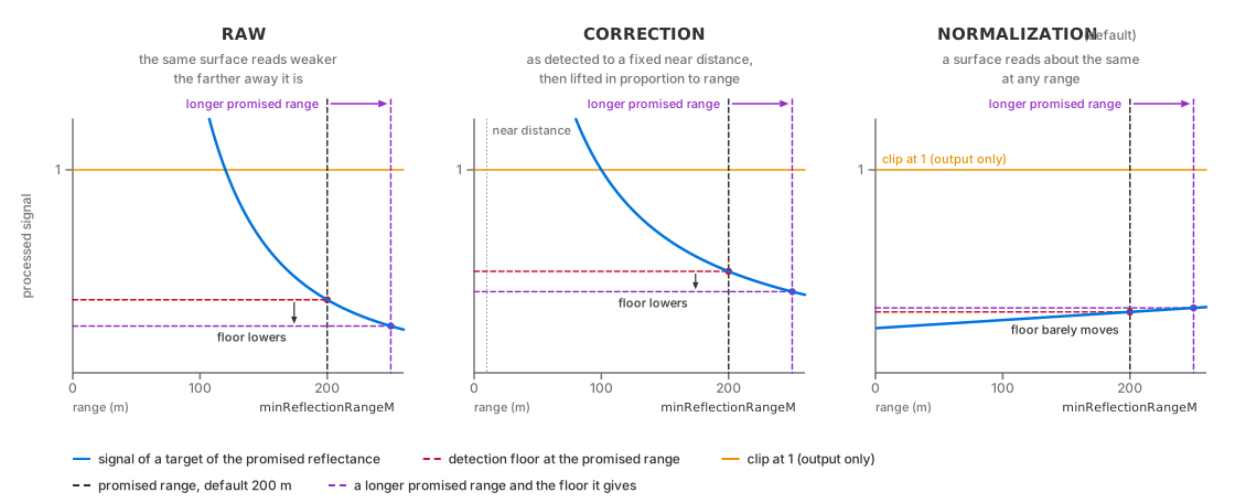
How the processed signal of a target of the reference reflectance changes
with range under each processing mode. The floor is derived at
minReflectionRangeM: under RAW and CORRECTION a longer reference
range meets a weaker signal and so lowers the floor, while under
NORMALIZATION the normalized signal is nearly flat and the floor barely
moves. The clip at 1 applies to the output only. Schematic, not to scale.#
Detection precedes output clipping to 1. If the threshold exceeds 1, strong
returns can still pass, but all report the maximum output intensity. Narrow
beam divergence can produce this condition for beam ray types; high
calibrationGain can produce it for any ray type.
Note
Surface response depends on its non-visual material label. See Non-Visual Sensor Materials for configuration.
A return behind a transmissive surface must exceed the detection threshold
after transmission losses on both the outward and return paths. Low
transmission can prevent detection. The front surface also produces a return,
so increase maxReturns to report surfaces behind it; see USD Attributes.
Beam properties#
peakPowerW and pulseTimeNs affect received energy. For beam ray types,
pulseTimeNs also affects echo separation; see minDistBetweenEchosM on
USD Attributes. focusDistM, Msquared, divergence and beam waist
define beam geometry. Intensity processing and detection thresholds use these
parameters for every ray type, including IDEALIZED. Units and definitions
are on USD Attributes.
The beam waist is the beam’s radius at its
focus, in meters. The divergence is the angle at which the beam spreads
beyond the focus, authored in degrees per axis. The beam quality factor
Msquared (M²) scales divergence relative to an ideal beam of the same
waist; 1 is ideal and the default is 1.4.
Divergence or beam waist#
Beam waist and divergence are related, per axis, by
divergence = M² · λ / (π · waist). Use the same length unit for wavelength
and waist. The result is in radians; convert it to degrees for comparison
with divergenceHorDeg and divergenceVerDeg.
If either value in one pair is zero and both values in the other pair are nonzero, the model derives both values of the incomplete pair. The default waists are 0.002 m and divergences are zero, so divergence is derived by default.
To specify divergence, set both angles and set the waists to zero. One zero waist is sufficient to derive both. Setting only one divergence angle while leaving the other zero causes both to be derived from the default waists, replacing the authored angle. At least one pair must be complete for this calculation.
If all four values are nonzero, the model retains them without reconciling
them. Intensity processing and IDEALIZED rays use those stored values.
GAUSSIAN_BEAM and UNIFORM_BEAM tracing uses divergence and a waist
derived from it, which can differ from the stored waist. To keep tracing and
intensity consistent, specify one pair and set the other to zero.
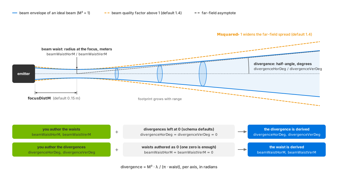
Waist, divergence and beam quality factor describe one beam. The waist is
the radius at the focus distance focusDistM; beyond it the footprint
grows along the divergence angle, and a beam quality factor above 1 widens
the far-field spread. Author one pair and the model derives the other
through divergence = M² · λ / (π · waist). Schematic, not to scale.#
Detector and mechanical noise#
Use measured or published detector values for aperture, quantum efficiency,
pixel pitch (micrometers), calibration gain and bit depth. aspectRatio
and pixelPitch determine collecting area. calibrationGain multiplies
the signal and can raise the detection threshold above the output clipping
level. See USD Attributes for definitions.
Mechanical-noise attributes perturb emitter direction and origin. See mechanical noise for controls, units and defaults.
Verification#
Read Intensity over [0, Counts[0]) and check for a nonzero value.
An empty output cannot satisfy this check. Count valid points using the
Flags bit 0x40, including when includeInvalidPoints is enabled.
See Outputs for channel definitions, Configure Lidar Output for
invalid-point handling and Sensor Outputs
for bounds on array reads.
Then move the detection floor and re-run against the same scene: raise
minReflectance and the valid count falls, lower it and the count rises, the
dimmest and most distant surfaces changing first. How many points a sweep
produces is scene-dependent and not reproducible; the direction of the change
is.
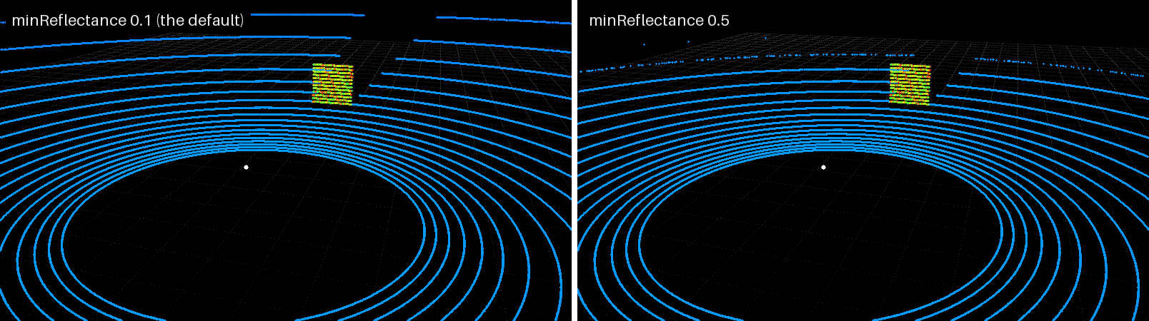
The same sweep colored by Intensity, on the left at the default floor
(minReflectance 0.1 at 200 m), on the right after raising
minReflectance to 0.5. The distant asphalt rings disappear first; the
cube, bright and near, keeps all of its points.#
Potential issues#
See the Symptom Index for additional causes and checks.
No returns from surfaces you know are within range: the detection floor is above them.
minReflectanceis too high, or, underRAW(andCORRECTIONwith the default beam),minReflectionRangeMis shorter than the distances in the scene. Under the defaultNORMALIZATIONwithIDEALIZEDrays the range barely moves the floor, so lowerminReflectanceinstead. Refer to the calibration pair.Intensities outside the expected numeric range: check
intensityScalePercentand the processing mode before changing beam or detector parameters.Every kept return reports the same, largest intensity (
intensityScalePercent/ 100 underLINEARmapping): every kept signal reached the clip at 1, as it must when the detection floor itself is above 1. With a beamrayTypea very narrow divergence can put the floor there, and a high detector gain can with any ray type.intensityScalePercentonly rescales the clipped value; look at the beam and detector numbers and at the calibration pair.Intensity changed after a change that “only” set the wavelength: expected.
waveLengthNmfeeds the photon conversion.Beam-derived quantities not what you computed by hand: both the divergence and the waist were non-zero, so neither was derived. Authoring only the divergence is enough for this, because the waists default to non-zero. Refer to divergence and beam waist.
Two close surfaces arriving as one return: they are closer together than the separation the ray type resolves. Refer to
minDistBetweenEchosMon USD Attributes.