

Build a Profile from a Spec Sheet#
Goal. Build a depth-camera profile from a vendor specification, separating measured values from estimates. Account for unit conversions and the near limit set by maximum disparity and product width.
Before you start. Have a working depth product and read the model’s capabilities and attributes. The lidar profile guide provides general profiling advice and three worked tutorials. The radar guide applies the method to radar; shared attributes covers sensor identity and timing.
The shape#
Published values initialize the product and validation against recorded data or a known scene makes the profile trustworthy; the lidar profile guide states the general advice in full. For a depth camera, optical dimensions and range limits can be taken from the datasheet. Confidence and noise also depend on the device’s matching algorithm, calibration and firmware post-processing. Public spec sheets rarely specify these in enough detail to determine model parameters, so tune those attributes and record them as tuned. The four source-confidence categories the lidar tutorials use (Source confidence) serve a depth profile just as well.
Map the spec sheet#
Every attribute of the model is authored on the RenderProduct, in one namespace
(where the schema applies). Configure the
Camera prim’s projection from the same camera calibration as the depth
attributes (matching the intrinsics).
The output resolution is the product’s own resolution. The frame rate of the
depth stream is the capture rate of the
Camera prim the product renders through: apply OmniSensorAPI to that prim
and author omni:sensor:frameRate on it (frame rate); an unscheduled camera renders one frame
per step. Either way the model produces its outputs for every frame the product
renders.
The depth-specific fields go into the omni:sensor:depthSensor: attributes below;
their types and defaults are in the generated schema reference. Most of the optics rows end in the
disparity the model
derives from each pixel’s distance.
Spec sheet field |
Attribute |
Notes |
|---|---|---|
Output resolution of the depth stream |
|
Match the published output resolution of the depth stream you are
modeling. The width enters the disparity; the near limit shows
what changing it does. The product and its |
Baseline |
|
The distance between the two simulated imagers, in millimeters. What the sign does and what a larger magnitude trades is in the optics group. |
Focal length in pixels |
|
Use the real camera’s calibrated horizontal focal length ( |
Reference image width |
|
Use the image width in pixels from the same calibration or camera mode
as |
Minimum depth, maximum depth or closest range |
|
Set the two limits from the datasheet range, in meters; they are
convenience cutoffs (range limits). The near end a
real device has comes from its maximum disparity, which is what
|
Confidence and noise claims: fill rate, depth accuracy, projector range |
|
These claims are not transcribed; they are what you tune against. Start
from the defaults and tune these attributes against measurements or
acceptance criteria such as the published accuracy and fill rate; public
spec sheets rarely provide enough detail to set them uniquely. The noise
attributes use rendered-image pixels; convert measured disparity steps,
jitter and spatial noise scales to that pixel grid. A
published infrared projector range is a starting value for
|
The near limit#
The maximum disparity determines the minimum distance accepted during
reprojection. A sample whose disparity exceeds maxDisparityPixel is
discarded. Because disparity is inversely proportional to distance, the
corresponding distance is calculated by inverting the disparity formula:
near_limit_m = width_px * baselineMM * focalLengthPixel
               / (sensorSizePixel * maxDisparityPixel * 1000)
With the schema defaults on a 1280-pixel-wide product, disparity is
49.335 / distance_m pixels (55 × 897 / 1000, with the width and sensor
size canceling). Disparity exceeds maxDisparityPixel = 110 at distances
below about 0.45 m. Because the default minDistance is 0.5 m, that distance
filter already excludes these samples and determines the effective near limit.
Increasing the product width to 2560 pixels with all other parameters unchanged
doubles disparity at every distance. The maximum disparity is then exceeded
below about 0.9 m, so it determines the effective near limit even though
minDistance remains 0.5 m.
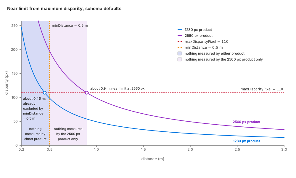
Effective near limit at two output resolutions. At 1280 pixels, the
0.5 m minDistance determines the near limit. At 2560 pixels, disparity
exceeds the 110-pixel maximum below about 0.9 m, which determines the near
limit.#
The effective near limit is the greater of minDistance and the distance
derived from the maximum disparity. To model a device’s published minimum range,
set minDistance to it and keep the disparity-derived distance at
or below it. With the product rendered at sensorSizePixel, the device’s own
disparity range in maxDisparityPixel does that by construction; at another
width with the same field of view, scale the disparity limit by the ratio of
product width to sensor size to preserve the near limit. Set maxDistance
from the far end of the datasheet range. These two distance attributes apply
explicit filters and define the visualization interval; their comparisons are
described under range limits.
Verify it worked#
Validate with simple scenes before using the profile in a full simulation. A profile that has not been checked against a known target is a set of transcribed numbers, not a sensor model.
Check the camera intrinsics and image dimensions. Confirm that
focalLengthPixelandsensorSizePixelcome from the same camera mode or calibration, and that their ratio agrees with the rendered camera’s field of view. Match the product resolution to the device’s output mode, or apply the pixel-unit conversions described above.Check the disparity at a known distance. Put a flat, textured target at a known distance in the center of the view and set
showDistance(the visualization attributes); use the readout to confirm the scene scale and thatbaselineMM,focalLengthPixel,sensorSizePixeland the product width reproduce the device’s disparity at that distance.Check the near limit. Read
DepthSensorDistanceat the center pixel while you move the target in: it should hold a value just beyond the published minimum range and read zero nearer (invalid measurements). Visualization mode 3 shows the same thing at a glance, because a pixel with no measurement is black there.Compare the input with the result. Visualization mode 4 shows the input depth before the simulation and mode 2 the simulated distance across the limits; switching
rgbDepthOutputModebetween them on the same scene shows where the simulation loses what the input had. ReadDepthSensorDistancefor numbers; the distance and disparity modes quantize values to eight bits and are diagnostic images, not measurements.Compare the depth output against recorded calibration targets where you have them: the same target geometry seen by the device and by the product, compared for range, coverage and the width of the holes around objects. Expect to tune the confidence and noise attributes to close the gap; that is what Tune Noise, Quantization and Confidence is for. The camera imagery itself is validated separately, against calibration targets, in Python: Camera calibration.
Render enough frames first. Warm the renderer up before you judge coverage; a product read too early shows dropouts that are not the profile’s (invalid measurements).
When it goes wrong#
A published field has no attribute to map onto. The matcher’s block size and
the vendor’s spatial, temporal or hole-filling filters belong to a matcher and
firmware the model does not simulate; the only such filter it has is the fixed
single-pixel cleanup that outlierRemovalEnabled switches (confidence
group). Record the gap
rather than forcing an approximate value into an unrelated attribute; the
lidar page says why.
Depth accuracy and fill-rate claims are a different case: they are not
transcribed either, but they are the targets the confidence and noise row of
the table is
tuned against.
Nothing is measured near the camera although minDistance allows it.
The maximum disparity decides the near end there, not the limit; the near limit works out
the distance at which it rejects samples and how to adjust it.
The profile behaves, but the numbers are subtly wrong. Confirm units against
USD Attributes: baselineMM is in millimeters, the two
limits and effectiveDistance in meters, and focalLengthPixel and
sensorSizePixel in pixels at the same reference image width. Check that
these intrinsics agree with the Camera prim, and that disparity and noise
parameters use the product’s pixel grid.