

USD Attributes#
The Lidar generic wpm model provides attributes for scan timing, beam and detector properties, return processing, material inputs and output encoding. Subsampling and capacity limits control computational cost and memory use. See Sensor API Schemas for complete attribute declarations and defaults.
Namespace and identity#
Apply OmniSensorGenericLidarWpmAPI to an OmniLidar prim. It includes
OmniSensorGenericLidarWpmFiringPatternAPI:p001 for the first firing pattern.
Apply additional instances, such as p002, to alternate between patterns.
The schema defaults omni:sensor:modelName to "LidarWpm",
omni:sensor:modelVendor to "NVIDIA" and omni:sensor:marketName
to "Generic". These use the shared omni:sensor:* namespace, as do
omni:sensor:frameRate, omni:sensor:startTime and
omni:sensor:frameLimit. On an OmniLidar, the model name selects the
lidar implementation; see Model identity and the shared attributes in
Sensor Configuration.
Model-specific attributes use omni:sensor:LidarWpm:*. The model ignores
omni:sensor:Core:* attributes. Its scan-type tokens are rotary and
solidState, not the Lidar generic core model’s ROTARY and SOLID_STATE.
See the lidar comparison.
Note
When a RenderProduct lists multiple lidars in rel camera, the first
sensor (tile zero) supplies the attributes for all tiles. See
Tile Lidars
for configuration details.
Scan schedule#
These attributes decide how often a scan completes, how a rotary scan sweeps, and how many returns one firing may yield.
Attribute |
Meaning and constraints |
|---|---|
|
Scans per second, as a rational pair |
|
|
|
Near end of the range window, in meters; at least |
|
Far end of the range window, in meters; greater than |
|
Offset, in degrees, added to both ends of the rotary azimuth window; it
turns the whole sweep about the sensor’s vertical axis. Default |
|
Start of the rotary azimuth window, in degrees. Default |
|
End of the rotary azimuth window, in degrees; default |
|
Nominal angular spacing of the rotary ticks, in degrees; positive,
default |
|
Number of consecutive ticks a firing pattern stays selected before the
next pattern in order takes over; positive, default |
|
Number of returns one receiver may report for one firing; positive,
default |
|
Workload-reduction factor; |
A rotary scan sweeps from validStartAzimuthDeg to validEndAzimuthDeg,
both shifted by startAzimuthOffsetDeg, within one scan period. Its ticks
are spread evenly over the window and the period, the first at the start of
the window and the last at its end, and every emitter row’s fireTimeNs
counts from the start of its tick. Which pattern a tick fires follows from the
tick index, firingPatternDwellTicks and the pattern count, in the order
described next; Configure a Firing Pattern
states the selection rule and works through examples.
Firing patterns#
A firing pattern is five parallel arrays under one instance name. It is the
counterpart of the Lidar generic core model’s emitter state: the emitter rows
fired in one tick, not the two-layer schedule that model calls a firing pattern
(Emitter state attributes on
its USD attributes). The namespace is exactly
omni:sensor:LidarWpm:firingPattern:<instance>:<property>, and each array
entry describes one emitter row: one emitter that fires at a given time within
the tick, in a given direction, into a given detector channel.
Property |
Meaning |
|---|---|
|
Azimuth of the row, in degrees, relative to the tick’s azimuth. |
|
Elevation of the row, in degrees. |
|
Firing time of the row, in nanoseconds, relative to the start of its tick; non-negative. |
|
Detector channel the row fires into: any unsigned integer, the vendor’s own label. The output reports it exactly as authored. |
|
Optional per-row range identifier; empty by default. An empty array selects the default range for every row. |
The four required arrays, azimuthDeg, elevationDeg, fireTimeNs and
channelId, must have the same non-zero row count, and rangeId must be
empty or that same length. An instance name starts with a letter or an
underscore and continues with letters, digits and underscores, so it may not
start with a numeral. Pattern instances are ordered lexicographically, so use
zero-padded names such as p001, p002 and p010; p10 would sort
before p2. At most 256 patterns are supported. The arrays are validated as
one set with the rest of the profile, so one malformed array keeps the whole
edit from being applied; Sensor Definition Validation describes the check you can run on a layer before
you render.
channelId accepts any uint value, including sparse and vendor-specific
labels, up to 4294967295. Memory use depends on the number of distinct
ids, not their numeric values. Point capacity depends on emitter rows retained
after subsampling, across every rotary tick or solid-state pattern. Rows
sharing an id still consume separate slots. Valid points report the authored
id unchanged; see Outputs.
Emitter and beam#
These attributes describe the pulse that leaves the sensor. The numeric ones must all be positive.
Attribute |
Meaning and constraints |
|---|---|
|
|
|
Peak power of one emitter, in watts. Default |
|
Wavelength of the emitted light, in nanometers; default |
|
Duration of the pulse, in nanoseconds; a whole number, default |
|
Focus distance of the sensor, in meters; default |
|
Beam-quality factor M²; |
|
Horizontal divergence of the beam, in degrees. Default |
|
Vertical divergence of the beam, in degrees. Default |
The peak power, wavelength, pulse duration, focus distance and divergences also enter the nominal signal the detection thresholds are expressed against; refer to the calibration point.
Changes to waveLengthNm take effect on the next scan.
Angular noise#
Angular noise changes each ray’s firing direction. The attributes under
omni:sensor:LidarWpm: specify four mean/standard-deviation pairs:
jitterAzimuthMeanDegandjitterAzimuthStdDevDeg: azimuth jitter.jitterElevationMeanDegandjitterElevationStdDevDeg: elevation jitter.offsetAzimuthMeanDegandoffsetAzimuthStdDevDeg: azimuth offset.offsetElevationMeanDegandoffsetElevationStdDevDeg: elevation offset.
For each ray, the model samples each pair’s normal distribution, adds the jitter and offset deviations for each axis, and rotates the ray accordingly. Both groups behave the same way:
A non-zero mean adds a constant angular bias.
A non-zero standard deviation adds per-ray noise.
All values are in degrees. Standard deviations must be non-negative.
All defaults are zero except jitterAzimuthStdDevDeg, which defaults to
0.005 degrees. Set it to 0 to disable the default angular noise.
Detector and detection thresholds#
These attributes describe the receiver and decide what counts as a return. Several of them matter only in one return-processing mode; the mode is described in the next section.
Attribute |
Meaning and constraints |
|---|---|
|
Effective aperture of the receiver, in meters; positive, default
|
|
Fraction of the arriving photons the detector converts, in |
|
Pitch of the detector pixels, in micrometers; positive, default |
|
Signal gain applied in a mode-specific way; non-negative, default
|
|
Resolution of the detector in counts, |
|
Shot-noise variance coefficient of the detector; non-negative, default
|
|
Width of one time-of-flight histogram bin in |
|
Number of time-of-flight bins kept per receiver in |
|
How far, in standard deviations of the pulse’s Gaussian shape, the
arriving pulse is deposited into neighboring bins; positive, default
|
|
Smallest deposited weight that still creates a bin; non-negative,
default |
|
Strict per-bin floor on the time-of-flight record, the one that forms
and splits its lobes, a lobe being a contiguous bump of that record;
non-negative, default |
|
Multiplier on the derived lobe-sum threshold in |
|
Full horizontal field of view of the detector, in degrees, in
|
|
Full vertical field of view of the detector, in degrees, in
|
|
Nominal Lambertian reflectance of the calibration case, in |
|
One-way range of the calibration case, in meters; positive, default
|
|
Minimum separation between two selected returns of one firing, in
meters; non-negative, default |
The detector field of view is rectangular in azimuth and elevation around the receiver’s boresight. Contributions outside either half-angle are rejected. Inside the field, sensitivity tapers smoothly from one at boresight to zero at the boundary, independently along each axis. Narrowing the field therefore reduces both coverage and sensitivity near its edges.
minDetectableReflectance and minDetectableReflectanceRangeM define a
noise-free Lambertian reference target at normal incidence. These attributes
specify reflectance and one-way range, not a detection probability. The model
uses the emitter, beam, aperture, detector and calibration parameters to derive
a nominal signal for this target.
waveformapplies the nominal signal multiplied bypeakSumThresholdScaleas the accumulated-lobe threshold.directDetectorapplies the unscaled nominal signal to each complete return.directMaterialrequires a return to reach the nominal threshold and exceeddirectMaterialIntensityThreshold.
peakPhotonThreshold is independent: it forms and splits waveform lobes and
sets a strict floor for each direct-detector return. Setting
minDetectableReflectance = 0 disables the derived threshold but preserves
explicit thresholds. See Choose a Return-Processing Mode for a comparison using
transmissive surfaces.
Return processing mode#
omni:sensor:LidarWpm:returnProcessingMode selects waveform (default),
directDetector or directMaterial. The direct modes require
rayType = idealized and maxReturns between 1 and 8.
waveform accepts either ray type and maxReturns between 1 and
255. Zero returns is invalid in every mode. See
Choose a Return-Processing Mode for signal processing and transmission behavior.
The outgoing path can interact with up to maxReturns surfaces in direct
modes, or min(2 * maxReturns, 10) surfaces in waveform mode. There is
no separate trace-depth control. Whether transmitted paths produce returns
also depends on the mode; see Choose a Return-Processing Mode.
directMaterial adds two attributes of its own, read in that mode only.
Attribute |
Meaning and constraints |
|---|---|
|
One-way reference distance of the mode’s range attenuation, in meters;
positive, default |
|
Normalized base-intensity threshold a return must exceed, in
|
Beyond directMaterialReferenceDistanceM, return strength falls with the
square of range. Closer hits use that reference distance for attenuation.
calibrationGain scales the result. A return must exceed
directMaterialIntensityThreshold and meet the calibration-point threshold.
Material inputs#
Surface response uses non-visual material labels.
omni:sensor:LidarWpm:useVisualMaterialInputs defaults to false.
When enabled, it also supplies the visual material’s diffuse reflectance,
roughness and shading normal to the non-visual material evaluation. Otherwise,
the model uses fallback values for these inputs. This is the model’s only
visual-material control.
Warning
useVisualMaterialInputs = true has a significant performance cost:
every material evaluation queries the visual material as well. Turn it on
when the visual material’s reflectance, roughness or normal detail is part
of what you model, and measure the cost on your own scene.
Changing the attribute while the sensor runs discards the scan in progress, like any edit that is not presentation-only, and needs no new start-up wait. Until the model is ready at start-up it publishes a well-formed empty output; Outputs describes it.
Output shaping#
These attributes control coordinates, motion compensation, invalid-point storage and publication timing. They do not change return detection.
Attribute |
Meaning and constraints |
|---|---|
|
|
|
|
|
Six finite values |
|
|
|
|
|
|
|
|
See Outputs for the six combinations of reference frame and motion compensation, coordinate encoding, and compact and dense layouts. The four coordinate attributes are presentation-only: updates re-encode detected returns at the next publication and preserve the scan. Editing any of the other three attributes discards the scan in progress. See Retune the Sensor While It Runs.
Motion compensation, and motion effects in general, need the renderer’s motion BVH; refer to Motion BVH and to the motion passage of Outputs.
Note
The other models carry their output controls under their own namespaces.
The Lidar generic core model has the same seven controls under
omni:sensor:Core:*, with a token-valued motion-compensation state
(Configure Lidar Output); the Radar
generic wpmDmat model has elementsCoordsType, outputFrameOfReference
and customFrameOfReferenceTrafo under omni:sensor:WpmDmat:* and no
motion-compensation attribute
(its USD attributes).
Intensity presentation#
Four attributes shape Intensity; all four are presentation-only, because
intensity is computed after detection (Intensity encoding).
Attribute |
Meaning and constraints |
|---|---|
|
|
|
|
|
Output full scale after processing and mapping; finite and
non-negative, |
|
Lookup values for the non-linear mapping types; every value finite,
empty by default. |
The formulas, the apparent-reflectivity convention, the lookup rule and the worked numbers are on Tune Intensity.
Tiling and subsampling#
omni:sensor:LidarWpm:tiledSubSampling reduces emitter rows without
shortening the scan. The retained count is the original row count divided by
the factor, rounded down. Selection spreads retained rows across the complete
rotary scan, or independently across each solid-state pattern. Only one
solid-state pattern fires per scan. Values 0 and 1 disable reduction.
Tiled products use tile zero’s factor for every sensor.
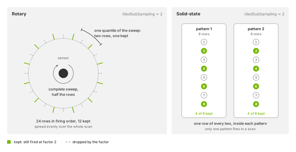
What a factor of 2 keeps: one emitter row of every two across the complete
sweep of a rotary scan (left), and one of every two inside each pattern of a
solid-state scan, of which one pattern fires per scan (right). Schematic; the
row counts are illustrative.#
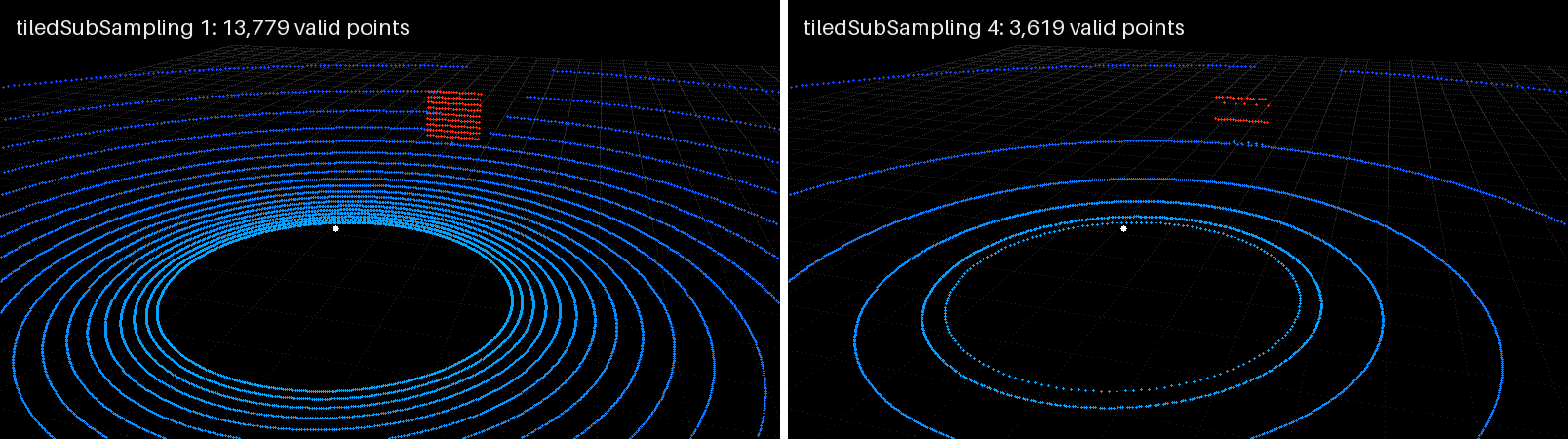
The same scene swept by one rotary sensor at tiledSubSampling = 1
(left) and at 4 (right), colored by Intensity: the right-hand
cloud keeps about a quarter of the rows, spread over the complete sweep, so
it is sparser but covers the same ground; each half states its valid point
count.#
The factor must leave at least one row in each solid-state pattern or in the whole rotary scan. An invalid initial factor prevents publication. An invalid runtime edit is logged and rejected; the last valid profile remains active. Subsampling also reduces point capacity. See Outputs for layouts and Tile Lidars for product configuration and tile ordering.
Capacity limits#
A configuration must stay within these bounds, which hold for the product as
a whole. The point capacity, the emitter rows the schedule keeps times
maxReturns times the number of tiles, may not exceed 2147483647 in
compact output (includeInvalidPoints = false) or 4294967295 in dense
output. In waveform mode the kept rows times the number of tiles times
sparseTofBinCapacity may not exceed 4294967295 either. Keep a
configuration within the bounds by lowering maxReturns,
sparseTofBinCapacity or the row counts, or by raising tiledSubSampling.
Runtime updates#
All omni:sensor:LidarWpm:* attributes support runtime edits. The eight
presentation-only attributes preserve the scan in progress. See
Retune the Sensor While It Runs for update effects and rejection behavior.
Performance#
Warning
These controls have the largest deliberate effect on the workload:
useVisualMaterialInputs = trueadds a visual-material query to every material evaluation.rayType = gaussianBeamtraces a beam of finite width rather than one idealized ray per emitter row.A smaller
rotPatternFiringResDeg, larger firing-pattern row counts, a largermaxReturnsand a largersparseTofBinCapacityeach add tracing work or storage.tiledSubSamplingreduces the retained workload.includeInvalidPointsat its defaultfalseadds a compaction step but reduces consumer work on sparse outputs;truetrades the compaction for a dense copy of every channel.
What each of these costs depends on the scene and the release, so measure it on your own workload.