

Camera generic core model#
The Camera generic core model processes a rendered HDR image through a fixed sequence of stages: photosite response, color filter array, sensor noise, bit-depth compression and image signal processing (ISP).
Configure these stages to produce sensor codes with a mosaic pattern and a chosen transport bit depth, or an ISP-processed RGB image. The model uses an existing rendered image; unlike non-visual sensors, it does not trace the scene itself.
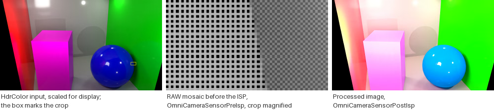
One Cornell box frame three times. Left, the rendered HdrColor input,
scaled for display, the small box marking the crop of the center panel;
center, that crop of the RAW mosaic before the ISP
(OmniCameraSensorPreIsp), magnified until each sensor code is one
photosite, where the blue sphere meets the green wall and the 2x2 pattern
changes with the color under it; right, the processed image after the ISP
(OmniCameraSensorPostIsp).#
What it simulates#
Where the model begins#
The Camera generic core model applies sensor and ISP post-processing to
HdrColor, the renderer’s linear, unclipped
high-dynamic-range image. The Cameras section and
its Outputs page describe the render modes and
AOVs produced by the renderer, including HdrColor, LdrColor, depth and
segmentation.
HdrColor is the model’s only input. The tone-mapped 8-bit LdrColor is
not an input. Configure the Input Image explains the
required HdrColor precision, the supported render modes and why
LdrColor is unsuitable.
What the model does to the image#
The operations run in a fixed order, the same every frame and for every camera, and the attributes you author decide how each one behaves. In order:
Color correction makes the rendered image look like what this sensor would have measured rather than what a neutral observer sees.
The color filter array collapses color to one sensor code per pixel, following the 2×2 mosaic you author, exactly as the physical filter mosaic over the photosites would.
Sensor noise adds photon shot noise, the randomness of photon arrival itself, and dark shot noise, from thermally generated carriers, to every code, random from one frame to the next; how each source scales with the signal is explained in the noise group of USD Attributes.
Companding compresses the wide internal code range onto the transport bit depth a sensor really sends. Rather than truncating, which would throw away the whole top of the range, it uses a piecewise-linear curve that spends codes generously on the dark end, where precision is needed, and sparingly on the bright end.
The ISP undoes what the sensor did, and then some: it expands the companded codes back to a linear range, reconstructs three color components per pixel from the mosaic, denoises and converts color, producing a YUV image that a final decode turns back into RGBA for display. It is the one stage that runs a program you supply rather than one assembled from attributes; Compand to a RAW Format and Run the ISP covers authoring one.
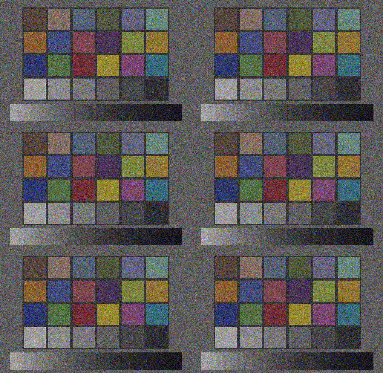
Photon shot noise on a color chart over ten consecutive frames: the grain is random from one frame to the next.#
Why the color filter array matters, on Author a Color Filter Array, explains what the color filter array’s 2×2 mosaic is for and what RCCB and the Bayer orderings trade against each other. Which pattern a sensor carries is a trade, and the trade is worth understanding before you author one.
What you get#
The model delivers its results as AOVs on the RenderProduct that renders the
camera, requested like any other camera output: through a RenderVar whose
sourceName names them (Output Configuration covers the RenderProduct and the
RenderVar). Seven names are reserved for the model. Two are
primary outputs, the images the
pipeline is built to deliver, and one of them must be requested; the other five
are optional diagnostic taps
that publish the image as it leaves one stage. Every product that requests any
of the seven must also request HdrColor, the model’s only input.
What arrives are image surface sized to the product’s display dimensions. While the input to the pipeline is a high-dynamic-range RGB image and the output is a low-dynamic-range RGB image, the intermediate image formats change along the pipeline and are not viewable without decoding Outputs gives each stage’s format, element type and shape, which primary output builds which pipeline, when a tap publishes and what switches the pipeline on.
Features at a glance#
One schema applied to the
Cameraprim you already render through, one input and one primary output requested on its RenderProduct, diagnostic taps where you want to watch a stage in the middle, and a check from the shape of what comes back that the sensor stages ran (Shape an Image Like a Camera Sensor).Three choices on the RenderProduct that decide what the model sees: that
HdrColoris requested on the same product as the model’s outputs, which floating-point precision it arrives in, and which render mode puts light into it; the 8-bitLdrColoris not an input (Configure the Input Image).Any 2×2 mosaic, authored as four weight triples with the semantic token that labels it and the maximal value that puts the codes into the range of the sensor’s bit depth (Author a Color Filter Array).
A RAW width, with the companding curve, pedestals and alignment that compress the codes onto it, and the ISP program that expands them again into the processed image (Compand to a RAW Format and Run the ISP).
The fixed order of the stages with the AOV each one publishes, each output’s format, element type and shape, and how products and cameras pair up (Outputs).
When to use it#
The model is for work that consumes camera data the way a sensor delivers it rather than the way a renderer does. Automotive and robotics perception stacks that take RAW frames can be fed from a simulated scene with the mosaic, the noise and the transport format of the sensor they were built for. ISP tuning and camera-perception algorithms can be validated against sensor-realistic imagery: a high-dynamic-range sensor covers a range wider than one exposure can by combining captures taken at different gains into one code space, and the noise model follows those zones; the same sensor works internally at 20 or 24 bits but transmits RAW8, RAW10, RAW12 or RAW14, and the companding stage reproduces that compression. And because every control is an attribute on the camera prim, sensor layouts can be compared on one rendered scene with nothing else changed, an RGGB mosaic against an RCCB one, for example.
What the model does not do#
The following settings and outputs are configured outside this model:
Lens geometry, depth of field, exposure time belong to the
Cameraprim’s own attributes (USD Attributes, Lens Calibration) and to the render mode; the model operates on the rendered result of those choices.Global illumination, reflections, shadows, denoising belong to the renderer (Render Modes).
Depth, disparity or stereo output is the Camera single-view stereo depth model, with its own outputs and its own input requirements; it is not this model.
Detections, returns, points, echoes are the non-visual models. This model produces image surfaces only: no counts, no returns, no per-point time offsets.
Pages under this model#
Use USD Attributes for the lower-case omni:sensor:core: controls,
How-To to configure the pipeline, and Outputs before mapping
images: it defines the primary outputs, intermediate formats and activation rules.