

USD Attributes#
The Lidar generic core model uses omni:sensor:Core:* attributes.
The sections below explain their units, constraints and interactions.
See Sensor API Schemas for the complete
declarations and defaults.
Sensor definition#
The model runs on an OmniLidar prim with OmniSensorGenericLidarCoreAPI
applied. That schema brings the shared sensor attributes and the first emitter
state, s001, with it; a sensor that alternates between firing patterns
applies OmniSensorGenericLidarCoreEmitterStateAPI:s002 and upwards for the
rest, as Configure a Firing Pattern shows in USDA.
The runnable lidar example authors the smallest useful prim: the schema, an
output coordinate system, a frame rate and a placement.
#usda 1.0
    def OmniLidar "Lidar" (
        prepend apiSchemas = ["OmniSensorGenericLidarCoreAPI"]
    )
    {
        token omni:sensor:Core:elementsCoordsType = "CARTESIAN"
        bool omni:sensor:Core:includeInvalidPoints = false
        double2 omni:sensor:frameRate = (10, 1)

        double3 xformOp:translate = (0, 0, 1)
        float3 xformOp:rotateXYZ = (90, 0, -90)
        uniform token[] xformOpOrder = ["xformOp:translate", "xformOp:rotateXYZ"]
    }
from pxr import Gf, Sdf

world = stage.DefinePrim("/World", "Xform")

lidar = stage.DefinePrim("/World/Lidar", "OmniLidar")
lidar.AddAppliedSchema("OmniSensorGenericLidarCoreAPI")
lidar.CreateAttribute(
    "omni:sensor:Core:elementsCoordsType", Sdf.ValueTypeNames.Token, custom=False
).Set("CARTESIAN")
lidar.CreateAttribute(
    "omni:sensor:Core:includeInvalidPoints", Sdf.ValueTypeNames.Bool, custom=False
).Set(False)
lidar.CreateAttribute("omni:sensor:frameRate", Sdf.ValueTypeNames.Double2, custom=False).Set(
    Gf.Vec2d(10.0, 1.0)
)
lidar.CreateAttribute("xformOp:translate", Sdf.ValueTypeNames.Double3, custom=False).Set(
    Gf.Vec3d(0.0, 0.0, 1.0)
)
lidar.CreateAttribute("xformOp:rotateXYZ", Sdf.ValueTypeNames.Float3, custom=False).Set(
    Gf.Vec3f(90.0, 0.0, -90.0)
)
lidar.CreateAttribute(
    "xformOpOrder",
    Sdf.ValueTypeNames.TokenArray,
    custom=False,
    variability=Sdf.VariabilityUniform,
).Set(["xformOp:translate", "xformOp:rotateXYZ"])
A sensor prim looks along its
local -Z with +Y up, and Orienting the prim explains that camera
convention, the output frame it is mapped onto and why the example authors
(90, 0, -90); the field-of-view section below says what the mapping means
for azimuths.
One RenderProduct per sensor. A RenderProduct of this model names one
sensor prim in its rel camera, and the model renders that sensor. To run
several sensors of this model, give each its own product, as the
independent-products pattern
shows. Step every product on every step
(Step every RenderProduct on every step).
Model-specific attributes use omni:sensor:Core:*. Emitter-state arrays
include the schema group and instance, for example
omni:sensor:Core:emitterState:s001:azimuthDeg. Shared identity and
scheduling attributes use omni:sensor:*. See
attribute namespaces
for naming rules and the effect of using an incorrect namespace.
Identification and scheduling#
The seven shared omni:sensor:* attributes are described on Sensor
Configuration. What is
specific to this model:
Applying
OmniSensorGenericLidarCoreAPIsetsomni:sensor:modelNameto"LidarCore",omni:sensor:modelVendorto"NVIDIA",omni:sensor:marketNameto"Generic"andomni:sensor:frameRateto(10, 1).omni:sensor:startTimeandomni:sensor:frameLimitkeep the shared defaults: zero seconds and no limit.On an
OmniLidar,omni:sensor:modelNameselects the lidar model, and the other two strings are labels the model does not read; model identity gives the rule. On this model"Generic"records that the prim carries the schema defaults, and the tutorials replace it with the device’s product name.omni:sensor:frameRateis how many complete scans the sensor finishes per second, as a rational Hz pair(numerator, denominator); its lidar meaning is under scheduling attributes.
Scanning principle#
omni:sensor:Core:scanType selects rotary (ROTARY, default) or
solid-state (SOLID_STATE) scanning. Most attributes apply to both types;
the table lists the scan-specific controls.
|
What it means |
What it brings with it |
|---|---|---|
|
A rotating lidar. The firing pattern is applied repeatedly around a full revolution. |
The angular step |
|
A solid-state lidar, flash lidars included. One tick per scan. |
The line structure of the pattern: |
omni:sensor:Core:rotationDirection applies to rotary sensors. CW
(clockwise) is the default; CCW reverses the sweep. At the start of each
scan period, the sweep passes 0 degrees: CW increases from 0 and CCW
decreases from 360. See angle conventions for firing and output azimuths.
scanType is fixed once the model is built: the model is built for one
principle, and an edit to the other is refused; refer to what stays fixed.
Ray type#
omni:sensor:Core:rayType chooses the shape of the ray each emitter
fires: IDEALIZED (the default), GAUSSIAN_BEAM or UNIFORM_BEAM.
An idealized ray either hits a surface or misses it. A beam has width, so it can straddle an edge: part hits the object and part reaches a surface behind it. One firing can therefore return two ranges. This is partial beam coverage.
The beam types distribute power differently:
GAUSSIAN_BEAMconcentrates power at the center. Losing the rim costs less signal than losing the center.UNIFORM_BEAMdistributes power evenly, like a plane wave. Signal falls with the fraction of the footprint lost.
Partial coverage is coarse, not continuous. A partly covered beam does not produce a proportionally dimmer return. See Tune Intensity and Point Drops for return weighting.
maxReturns reads differently for the two kinds of ray. Along an idealized
ray the model keeps the first maxReturns surfaces it meets; for a beam it
keeps the maxReturns strongest returns, after hits at nearly the same range
have merged into one. Beam ray types cost substantially more to trace than
idealized rays, so start with IDEALIZED and switch only when an edge effect
or a partial return is what you are studying; the tutorials do the same.
The beam geometry attributes, beamWaistHorM, beamWaistVerM,
divergenceHorDeg, divergenceVerDeg and Msquared, build the beam for
the two beam ray types. They are not ignored for an idealized ray: the intensity
processing and the detection threshold read the waist, the divergence and the
beam quality factor whatever the ray type. Beam properties below describes them.
rayType is read when the model is built. Author it before the sensor first
produces, and recreate the sensor to change it; refer to what stays fixed.
Firing pattern#
A firing pattern defines the scan rate, rotary angular step, emitter count
and detector count. Per-emitter directions, firing times and detector
assignments are authored through instances of the multiple-apply
OmniSensorGenericLidarCoreEmitterStateAPI schema on the same sensor prim.
A tick is one application of the firing pattern. Rotary ticks are spaced by
rotPatternFiringResDeg; a solid-state scan has one tick.TickIdidentifies the tick that produced each point, starting from zero.An emitter represents a laser. At each tick, every emitter in the active state fires with azimuth offset
azimuthDeg, absolute elevationelevationDegand delayfireTimeNsfrom the tick’s start. Points from one tick can have different measurement times, reported byTimeOffsetNs.A channel represents a detector.
numberOfChannelssets the detector count;channelIdassigns each emitter to a detector. Output channels, such as theChannelIdtensor, are described on Outputs.An emitter state is an instance of
OmniSensorGenericLidarCoreEmitterStateAPI. The main sensor schema includesOmniSensorGenericLidarCoreEmitterStateAPI:s001. Apply additional instances, such asOmniSensorGenericLidarCoreEmitterStateAPI:s002, to cycle through multiple sets of per-emitter values.A scan is one complete pass of the pattern.
omni:sensor:frameRatesets the number of scans per second.A return is one detected point. A firing can produce zero or more returns.
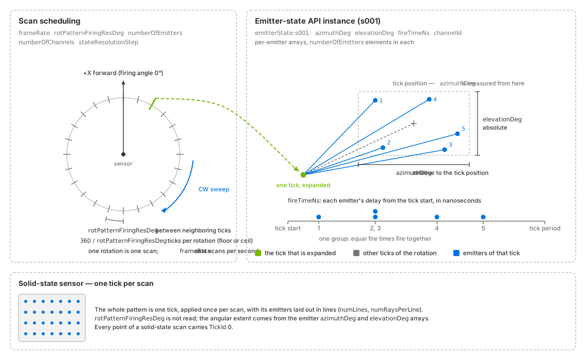
Rotary ticks are spaced by rotPatternFiringResDeg. The emitter state
defines each emitter’s direction and firing time within a tick.
A solid-state sensor (lower panel) applies its pattern once per scan.#
See Configure a Firing Pattern for array-length and firing-time requirements, flash-lidar configuration and cycling through emitter states.
Scheduling attributes#
Attribute |
Type |
Default |
What it does |
|---|---|---|---|
|
|
|
The scan rate, as rational Hz: how many complete scans happen per second. |
|
|
|
Scans are counted from it. |
|
|
|
The angular step, in degrees, at which a rotary sensor applies its pattern; a solid-state sensor does not read it. |
|
|
|
Caps how many returns are kept per channel for one firing. |
|
|
|
The number of emitters per emitter state, and so the length of every non-empty per-emitter array. |
|
|
|
The number of detectors. |
|
|
|
How many consecutive rotary ticks, or consecutive solid-state scans, reuse the same emitter state before the model advances to the next. |
|
|
|
The number of lines of a solid-state pattern; a rotary sensor leaves it at its default. |
|
|
|
One element per line saying how many emitters it holds, so the elements
add up to |
omni:sensor:frameRate is the scan rate, as rational Hz: (10, 1) is ten
complete scans per second, and scans are counted from omni:sensor:startTime.
A scheduled scan needs a rate of at least 0.466 Hz; lower positive rates are
rejected, for the reason the minimum scan rate gives where the firing pattern is authored. A
rate of zero, (0, 1), is not rejected: the model treats it as unset and
flashes a whole scan in every capture, as if instantLidar were set
(Instant lidar). The renderer then captures the
sensor on its default schedule, described under
Frame rate, step and delivery.
omni:sensor:Core:rotPatternFiringResDeg is the angular step, in degrees, at
which a rotary sensor applies its pattern (default 0.1); a solid-state
sensor does not read it. The scan rate and the angular step are independent
knobs that together set the tick rate, so a finer step or a faster scan
shortens each tick. Because q = 360 / rotPatternFiringResDeg need not be a
whole number, a rotation’s tick count is not fixed, and a nominal tick count
must not size a per-rotation buffer; fractional ticks on Configure a Firing Pattern states the rule, with the tick-rate consequence for
fire times.
omni:sensor:Core:maxReturns caps how many returns are kept per channel for
one firing (default 2). Which ones are kept depends on the ray type, as
ray type describes.
A transmissive surface is itself a return, so seeing past it generally means
raising maxReturns.
omni:sensor:Core:numberOfEmitters is the number of emitters per emitter
state (default 128), and so the length of every non-empty per-emitter
array. omni:sensor:Core:numberOfChannels is the number of detectors
(default 128). The two counts do not have to agree: several emitters may
report into one detector, and a sensor may have detectors no emitter uses.
Warning
A solid-state sensor needs numberOfChannels to be at least
numberOfEmitters. Keep the two equal unless the device really has more
detectors than emitters.
omni:sensor:Core:stateResolutionStep (default 1) is how many
consecutive rotary ticks, or consecutive solid-state scans, reuse the same
emitter state before the model advances to the next. It matters only with
several states; a sensor with a single firing pattern needs no change.
omni:sensor:Core:numLines (default 0) and
omni:sensor:Core:numRaysPerLine (default empty) describe the line structure
of a solid-state pattern: the number of lines, and one element per line saying
how many emitters it holds, so the elements add up to numberOfEmitters. A
rotary sensor leaves them at their defaults. Validation holds them to each
other and to the per-emitter bank array, as parameter validation lists.
The model counts the
instances of OmniSensorGenericLidarCoreEmitterStateAPI applied to the prim
and cycles through them in the lexicographic order of their instance names, so
keep the numbers zero-padded: s001, s002, s010.
Emitter state attributes#
Every attribute of an emitter state is prefixed
omni:sensor:Core:emitterState:s#:, where s# is the instance name,
s001 for the state the model’s schema applies. Four arrays are required and
hold numberOfEmitters elements each; the rest hold numberOfEmitters
elements or are empty, and empty means “this state does not use that
correction”. Array-length requirements
says what the schema’s 128-element defaults do when you change
numberOfEmitters.
Attribute |
Type |
Default |
What it does |
|---|---|---|---|
|
|
128 elements; see the schema reference; full defaults are in the schema shipped in the ovrtx package |
Required: the emitter’s azimuth relative to the tick position, in degrees. |
|
|
128 elements; see the schema reference; full defaults are in the schema shipped in the ovrtx package |
Required: the emitter’s absolute elevation, in degrees. |
|
|
128 elements; see the schema reference; full defaults are in the schema shipped in the ovrtx package |
Required: the emitter’s delay from the tick’s start time, in nanoseconds. |
|
|
128 elements; see the schema reference; full defaults are in the schema shipped in the ovrtx package |
Required: names the detector each emitter reports into, as the vendor numbers it. |
|
|
|
The line the emitter belongs to, counted from |
|
|
|
The range region the emitter uses, counted from |
|
|
|
The emitter’s origin, offset vertically from the sensor origin, in meters. |
|
|
|
The emitter’s origin, offset horizontally from the sensor origin, in meters. |
|
|
|
A per-emitter range correction, in meters, subtracted from the ranges that emitter reports. |
|
|
|
Per-emitter peak power, in watts; an authored entry above 1e-5 W
overrides the sensor-wide |
|
|
|
Which emitters a state flagged |
|
|
|
Marks a region-of-interest state: it fires the emitters flagged in
|
|
|
|
Declared per emitter and checked for length with the other arrays, but nothing in ovrtx reads it. |
|
|
|
Declared per emitter and checked for length with the other arrays, but nothing in ovrtx reads it. |
The required direction and timing arrays are:
azimuthDeg(float[]): azimuth offset from the tick position, in degrees. The tick position rotates for rotary scans and remains aligned with the sensor’s forward direction for solid-state scans.elevationDeg(float[]): absolute elevation, in degrees.fireTimeNs(uint[]): firing delay from the tick’s start, in nanoseconds. Values must be nondecreasing and must not exceed the tick period. A solid-state tick spans one scan. Equal values fire simultaneously; see firing-time requirements.
The required channelId (uint[]) array assigns a detector ID to each
emitter. IDs can use any numbering in [0, 4294967295], including sparse
or vendor-specific values. Across all emitter states, the number of distinct
IDs must not exceed numberOfChannels. ID values do not index the model’s
storage, so larger or sparse IDs do not increase memory use. Valid returns
report the authored ID unchanged in ChannelId.
The default state uses IDs 1 through numberOfChannels. If your
application indexes a table with ChannelId - 1, validate that IDs fall
within that range; zero and out-of-range IDs are unsafe for this indexing
scheme. See ChannelId output for unwritten slots and
valid-entry filtering.
The optional arrays:
bank(uint[]): the line the emitter belongs to, counted from0. Every value must be belownumLines, whose default is0, so authoringbankneedsnumLinestoo, whatever the scan type.rangeId(uint[]): the range region the emitter uses, counted from0. Every value must be belowrangeCount, with arangeCountof0counted as1; the regions themselves,rangesMinMandrangesMaxM, are described under field of view, range and orientation.vertOffsetMandhorOffsetM(float[]): the emitter’s origin, offset vertically and horizontally from the sensor origin, in meters. What the offset does to the traced rays and to the delivered coordinates is under emitter offsets on Outputs.distanceCorrectionM(float[]): a per-emitter range correction, in meters, subtracted from the ranges that emitter reports.emitterPeakPowerW(float[]): per-emitter peak power, in watts. An authored entry above 1e-5 W overrides the sensor-widepeakPowerWfor its emitter; any other entry, zero included, falls back to it.roi(bool[]) and the scalarisROIState(bool, defaultfalse): a region-of-interest pattern. A state flaggedisROIStatefires the emitters flagged inroionly while the tick lies inside the interval fromminAzimuthROItomaxAzimuthROI, described under field of view, range and orientation.focalDistMandfocalSlope(float[]): declared per emitter and checked for length with the other arrays, but nothing in ovrtx reads them; refer to declared but not read.
Field of view, range and orientation#
This group decides which returns are delivered. Each limit is a validity limit:
a return outside it is not a valid point, so by default it is dropped from the
point cloud, and with includeInvalidPoints it arrives as an invalid entry.
The procedure, the window mechanism and how to verify what arrives are on
Constrain the Field of View.
Attribute |
Type |
Default |
What it does |
|---|---|---|---|
|
|
|
Near limit of the range band, in meters; a surface closer than it is as
absent from the point cloud as one beyond |
|
|
|
Far limit of the range band, in meters; it also bounds how far any ray is traced. |
|
|
|
The number of range regions |
|
|
|
With |
|
|
|
With |
|
|
|
Start of the rotary field of view, in degrees, measured on the firing
angle before |
|
|
|
End of the rotary field of view, in degrees; when the start is greater than the end, the window wraps through 360 degrees. |
|
|
|
Start of the interval in which ROI-tagged emitter states participate,
in degrees, tested against the tick position; |
|
|
|
End of that interval, in degrees; an interval whose start is greater than its end wraps through 360 degrees, and authoring an ROI does not narrow the point cloud. |
|
|
|
The distance along every ray within which objects are invisible, in meters; the control for a sensor that sits inside another object. |
|
|
|
The range error scale, in meters: the model adds Gaussian range error
scaled by it, and the error grows with the return’s distance relative
to |
|
|
|
Declared as a distance quantization step, in meters, but the model does not read it, so in ovrtx it has no effect. |
|
|
|
The minimum distance between two echoes for them to be resolved separately, in meters; also a second near limit, because a firing’s first return is measured against the sensor itself. |
|
|
|
Scales the material’s reflected share when a firing continues past a surface for the next return. |
|
|
|
Scales the material’s transmitted share when a firing continues past a surface for the next return. |
|
|
|
The start azimuth offset of the sensor, in degrees; on a rotary sensor it is added to every firing direction, so delivered azimuths include it, while the valid-azimuth window is measured before it is added. |
nearRangeM and farRangeM define the accepted range interval in meters,
with defaults of 0.3 and 200. Returns outside it are invalid.
farRangeM also limits tracing distance. See
the range band for examples.
rangeCount (default
0), rangesMinM and rangesMaxM (float[], in meters, with
rangeCount elements each) define range regions, and each emitter’s
rangeId selects one. Once you author them, the window an emitter’s
rangeId selects is the validity test for that emitter’s returns instead of
the band; farRangeM still bounds the trace. With the arrays authored,
rangeCount must equal the length of each, with 0 counted as 1, or
the whole parameter set fails validation.
validStartAzimuthDeg
(default 0) and validEndAzimuthDeg (default 360) apply to rotary
sensors only; a solid-state sensor takes its angular extent from the emitter
azimuth and elevation arrays. When the start is greater than the end, the
window wraps through 360 degrees. The window is measured on the firing angle,
the tick position plus the emitter’s azimuth, clockwise from the sensor’s
forward axis and before startAzimuthOffsetDeg is added, not on the azimuth
the output reports: with no offset, a window from 0 to 90 degrees delivers
azimuths from -90 to 0 degrees. The azimuth window gives the conversion for checking delivered
points against it.
minAzimuthROI and maxAzimuthROI (default 400 each, in
degrees) define the interval in which ROI-tagged emitter states participate in
a foveated or multi-state pattern, together with isROIState and the
per-emitter roi array described above. The default of 400 means that no
ROI is configured; author both limits to configure one, and an interval whose
start is greater than its end wraps through 360 degrees. The interval is tested
against the tick position, before the emitter’s own azimuth and
startAzimuthOffsetDeg are added. Authoring an ROI does not narrow the point
cloud, and the untagged states of the pattern are not confined to the interval;
the azimuth pair is what narrows the cloud.
![Two top-down views of a rotary sensor. Left: the firing angle measured clockwise from the sensor's forward axis, before startAzimuthOffsetDeg, with the validStartAzimuthDeg to validEndAzimuthDeg window and the ROI interval drawn as arcs, and arrows showing the CW and CCW sweep directions. Right: the delivered azimuth measured counter-clockwise from the forward axis in the range (-180, 180], including startAzimuthOffsetDeg.](../../../_images/lidar_core_azimuth_conventions.svg)
Angle conventions of a rotary sensor seen from above. The firing angle
(left) runs clockwise from the forward axis, before the start offset is
added; the validity window is measured on it, the ROI interval on the tick
position it starts from, and the sweep runs CW or CCW along it. The
delivered azimuth (right) runs counter-clockwise from the forward axis in
(-180, 180] and includes startAzimuthOffsetDeg.#
rangeOffsetM (default 0.0) is the
distance along every ray within which objects are invisible, in meters: the
trace starts that far out from the emitter, so a surface inside the offset is
never hit, while reported ranges stay measured from the emitter. It is the
control for a sensor that sits inside another object, such as a housing or a
bumper. rangeAccuracyM (default 0.02) is the range error scale, in
meters: the model adds Gaussian range error scaled by it, and the error grows
with the return’s distance relative to farRangeM.
rangeAccuracyM controls simulated range uncertainty. rangeResolutionM
is declared as a distance quantization step (default 0.004 m), but the
model does not read it. It has no effect on delivered coordinates.
minDistBetweenEchosM (default 0.4)
is the minimum distance between two echoes for them to be resolved separately,
in meters. It is also a second near limit, because a firing’s first return is
measured against the sensor itself. With IDEALIZED rays a first return
nearer than this distance is therefore dropped even inside the range window,
and nothing farther along that firing’s path is reported either; whichever of
nearRangeM and minDistBetweenEchosM is farther is the near limit that
applies. Later returns along the ray are measured against the previous kept
return, so two surfaces resolve separately only when they are at least this
far apart. With GAUSSIAN_BEAM or UNIFORM_BEAM, whose returns are ranked
strongest first, each return is measured against the one ranked just before it
if that one was kept, and against the sensor otherwise, and the separation two
surfaces need is the larger of minDistBetweenEchosM and half the distance
light travels in pulseTimeNs, so a long pulse can merge close returns.
Multiple returns share the power. When maxReturns allows more than one
return, a firing that meets a surface continues past it to look for the next,
by reflection or by transmission, whichever carries more power once two factors
have scaled the material’s reflected and transmitted shares:
reflectionPowerFraction (default 0.5) scales the reflected share and
transmissionPowerFraction (default 1.0) the transmitted share. The
continuing firing carries that scaled share, so later returns come back weaker
than the first. How a surface reflects or transmits at the sensor’s wavelength
comes from its material label; refer to Non-Visual Sensor Materials.
Orientation. startAzimuthOffsetDeg (default 0.0) is the start
azimuth offset of the sensor, in degrees. On a rotary sensor it is added to
every firing direction, so delivered azimuths include it, while the
valid-azimuth window is measured before it is added, as the figure above shows.
A solid-state sensor’s firing directions do not include it. The angles
themselves live in the sensor frame that Sensor Outputs defines, with azimuth 0 straight
ahead and positive delivered azimuth to the left; Orienting the prim says how the prim’s
camera-style axes are mapped onto that frame and gives the rotation the
examples author.
Intensity, detection floor, beam and detector#
These attributes control return detection and reported Intensity values.
The model applies the detection threshold before clipping the processed signal
to [0, 1] and mapping and scaling it for output. See Tune Intensity and Point Drops
for configuration and verification.
Intensity output#
Attribute |
Type |
Default |
What it does |
|---|---|---|---|
|
|
|
Decides what the delivered intensity number means: |
|
|
|
Maps the clipped value onto the delivered one: the delivered intensity
is the model’s value times |
|
|
|
Layers a lookup on top, to emphasize particular regions of the
intensity range; |
|
|
|
The table the clipped value is looked up in before the scaling; a table
with fewer entries than |
|
|
|
Carried on the prim for a consumer that decodes the delivered values; the model does not apply it to what it delivers. |
omni:sensor:Core:intensityProcessing selects how the detector signal is
processed relative to the calibration signal defined by minReflectance
and minReflectionRangeM. The detector signal depends on the pulse,
wavelength, detector parameters and the material response at that wavelength.
RAW: uses the detector signal relative to the calibration signal, without range normalization. Return intensity decreases with distance.NORMALIZATION(default): compensates for beam spreading with distance fromfocusDistM.CORRECTION: applies a range-proportional factor beyond a fixed near distance. Nearer returns receive no range correction.
For beam ray types, all modes normalize by the returned fraction of the beam,
so partial beam coverage does not proportionally reduce intensity. All modes
also apply an aperture factor that reduces the signal when the beam footprint
exceeds effectiveApertureSizeM; this factor never increases the signal.
The processed signal is tested against the detection threshold before being
clipped to [0, 1] for output.
intensityMappingType selects the mapping applied to the clipped value:
LINEAR(default) andNONLINEAR_DECODING_ONLYleave it unchanged.NONLINEARandNONLINEAR_ENCODING_ONLYuseintensityMappingEncoding. For a table with count entries, the lookup index is floor(value × (count − 1)). If count is less thanintensityScalePercent, the table entry is added to the clipped value. Otherwise, the entry replaces it.
After mapping, the value is multiplied by intensityScalePercent / 100.
The default scale is 255, so a saturated return with linear mapping
produces an intensity of 2.55.
intensityMappingDecoding stores a decoding table for consumers; the model
does not apply it to the output. Both mapping tables are float[] arrays
of arbitrary length, empty by default.
Detection floor#
Attribute |
Type |
Default |
What it does |
|---|---|---|---|
|
|
|
Reference target reflectance, expressed as a fraction. Together with
|
|
|
|
The range of the calibration point, in meters. |
The model derives its detection threshold from a reference target with
reflectance minReflectance at distance minReflectionRangeM.
See detection thresholds for the effect
of each processing mode, thresholds above the output clipping level and
other return-rejection conditions.
Beam properties#
Beam attributes define emitted power, wavelength, pulse duration and beam geometry. For beam ray types, pulse duration also affects echo separation.
Attribute |
Type |
Default |
What it does |
|---|---|---|---|
|
|
|
Peak emitted optical power per emitter, in watts; a per-emitter
|
|
|
|
Emitter wavelength, in nanometers, used in photon conversion. |
|
|
|
Pulse duration, in nanoseconds. Scales received photon count and affects echo separation for beam ray types. |
|
|
|
Beam focus distance, in meters; the reference distance for range normalization. |
|
|
|
Beam quality factor M², used in waist/divergence conversion and intensity normalization. |
|
|
|
Horizontal beam waist at the focus, in meters. |
|
|
|
Vertical beam waist at the focus, in meters. |
|
|
|
Horizontal beam divergence, in degrees. Derived from the waist by default. |
|
|
|
Vertical beam divergence, in degrees. |
Specify either beam waist or divergence for each axis. The model derives the
other using wavelength and Msquared; by default it derives divergence
from the waists. See waist and divergence for the calculation and precedence
when both are authored, and ray types for their use in tracing.
Per-emitter power overrides are listed under
emitter-state attributes.
Detector properties#
Detector attributes control conversion of received light into a signal. Use device specifications or calibration measurements where available.
Attribute |
Type |
Default |
What it does |
|---|---|---|---|
|
|
|
The aspect ratio of the detector; it scales the detector area that collects the received signal and the background light. |
|
|
|
Effective receiver aperture, in meters. Reduces the signal when the beam footprint exceeds it. |
|
|
|
The detector’s quantum efficiency. |
|
|
|
The detector’s pixel pitch, in micrometers. |
|
|
|
The detector’s calibration gain. |
|
|
|
The detector’s bit-depth resolution. |
Mechanical noise#
Mechanical noise perturbs beam direction and origin. Each component has a mean and standard deviation. A nonzero mean introduces a fixed bias; a nonzero standard deviation adds random variation. Origin noise can model vibration.
Attribute |
Type |
Default |
What it does |
|---|---|---|---|
|
|
|
Mean emitter azimuth error, in degrees. |
|
|
|
Standard deviation of emitter azimuth error, in degrees. |
|
|
|
Mean of the emitter’s elevation error, in degrees. |
|
|
|
Standard deviation of the emitter’s elevation error, in degrees. |
|
|
|
Mean of the emitter’s origin error as |
|
|
|
Standard deviation of the emitter’s origin error as |
Output shaping and cadence#
These attributes select output coordinates, reference frame, motion compensation, invalid-point handling and scan delivery. See Outputs for tensor layouts, timestamps and frame metadata, and Configure Lidar Output for configuration examples.
Attribute |
Type |
Default |
What it does |
|---|---|---|---|
|
|
|
The coordinate system of the |
|
|
|
The frame every output is expressed in: |
|
|
|
The custom frame as |
|
|
|
Whether the sensor’s own motion during the scan is removed from the delivered coordinates; it does not enable the renderer’s motion BVH by itself. |
|
|
|
Include invalid output entries. |
|
|
|
Deliver partial scans on each step instead of waiting for a complete scan. |
|
|
|
Trace a complete scan at each step’s start time. Uses the start pose with motion BVH enabled, or the frame-end pose otherwise. |
Coordinate representation and reference frame are independent.
elementsCoordsType affects only Coordinates. HitNormal and
Velocity remain Cartesian and are rotated into outputFrameOfReference
without translation. See output coordinates.
outputMotionCompensationState selects whether to compensate for the
sensor’s motion during a scan:
NONCOMPENSATED(default) retains motion distortion.COMPENSATEDuses each point’s timestamp and the sensor’s motion to transform it into the requested output frame.HitNormalandVelocityfollow the same compensation state.
Motion effects require the renderer’s motion BVH, selected at renderer creation. See Motion Artifacts for configuring both settings.
includeInvalidPoints = false delivers valid returns only. With true,
all slots are delivered; use Flags to select valid entries as described
on Outputs.
partialOutputs = false accumulates a complete scan and delivers it on the
step that finishes it. Intermediate steps produce no output for the product.
With true, each step delivers the portion covered by that step’s time
interval. omni:sensor:frameRate sets the scan period; see
Sensor Scheduling for scheduling and delivery.
instantLidar = true traces an entire scan at the start of each step.
With motion BVH enabled, tracing uses the step’s start pose; otherwise it
uses the frame-end pose. Authored firing times are ignored during tracing
but still validated. A solid-state sensor can trace a zero-length interval if its end
time is greater than zero; a rotary sensor requires a positive-length interval.
In this mode, partialOutputs controls which steps deliver the complete
scan. See instant lidar for usage
and Outputs for timestampNs and TimeOffsetNs behavior.
Runtime updates#
See Runtime Parameter Updates for submitting edits, rejected updates and changes to output requests. The following rules apply to this lidar model.
Output settings, including includeInvalidPoints and partialOutputs,
and intensity-mapping tables support runtime edits. Changes to maxReturns,
emitter/channel counts, rotPatternFiringResDeg, frame rate or table lengths
can rebuild buffers without resetting the frame counter.
Accumulated points are retained unless an edit changes tick or channel
identity; those edits discard the partial scan. With partialOutputs = false,
mid-scan edits to coordinate type, reference frame, custom transform or motion
compensation apply to the entire delivered scan. See
runtime output changes.
scanType and rayType require model recreation:
Changing
scanTypeis rejected with an error, along with all other edits in that update. The rejected value may remain authored. Later updates are checked against the active scan type and can apply if otherwise valid.rayTypeis read during initialization. A running model cannot switch betweenIDEALIZEDand beam ray types.
Recreate the sensor to change these settings. A RenderVar change that rebuilds the model reads both from the current authored values. A buffer rebuild caused by resizing retains the existing scan and ray types.
Parameter validation#
The model validates attribute types and the complete parameter set at creation and on every update. It checks these constraints:
every non-empty per-emitter array holds
numberOfEmitterselements (array-length requirements);fire times never decrease within a state, and the last one fits inside one firing period: one tick for a rotary sensor, one scan for a solid-state one (fire-time order);
the emitter states together use no more distinct channel ids than
numberOfChannels(channel ids);rangesMinMandrangesMaxM, when authored, haverangeCountentries, with arangeCountof0counted as1, and everyrangeIdis belowrangeCount(the range band);every
bankis belownumLines, and on a solid-state sensornumRaysPerLinehasnumLinesentries whose sum equalsnumberOfEmitters(scheduling attributes and emitter state attributes);a positive frame rate is at least 0.466 Hz (the minimum scan rate).
For a valid definition, the validation utility reports the authored frame rate and start time, capture duration, frame limit and partial-output policy. Capture duration is one scan period, or zero with instant lidar.
A rejected runtime update preserves the previous parameters and output layout. The validation utility reports the reason when run on the same parameter set; see Runtime Parameter Updates.
Invalid initial parameters prevent initialization and produce no output. The reason is logged as an error. Correct the parameters to initialize the sensor on the next step.
Declared but not read#
The following attributes are declared but have no effect in this model:
omni:sensor:Core:emitterStatesFile(string, default empty). Use emitter-state API instances instead; see Configure a Firing Pattern.omni:sensor:Core:rangeResolutionMadds no error and changes no delivered coordinate; refer to accuracy versus resolution.focalDistMandfocalSlope: per-emitter arrays checked for length but not used in simulation.omni:sensor:encryption:params: see shared sensor attributes.
Tick rate is derived from omni:sensor:frameRate and
rotPatternFiringResDeg; there is no separate tick-rate attribute. See
scan scheduling.