

Camera single-view stereo depth model#
The Camera single-view stereo depth model simulates stereo depth measurements from one rendered view. It post-processes the renderer’s color, distance and position outputs.
A stereo depth camera does not measure distance directly. It photographs the scene from two places a known baseline apart, matches the two pictures, and turns the horizontal displacement between matching pixels, the disparity, into a distance. Everything that makes such a camera hard to use follows from that: no depth where the two views disagree, because one imager sees what the other cannot; no depth where a surface is too smooth to match; coarse depth far away, because one pixel of disparity spans more distance the farther the surface is; and a distance that is quantized rather than continuous.
The Camera single-view stereo depth model reproduces those consequences from a single rendered view. It takes the distance the renderer already computed for each pixel, converts it to a disparity, reprojects it to the pixel where a second imager would have seen it, adds disparity noise and quantization, and discards everything a real matcher could not have recovered. If you want to mimic an active stereo camera, a simulated infrared projector accepts untextured surfaces within a distance you set. The result is a depth image that behaves like a stereo camera’s, with no second render and no matching algorithm.
What it simulates#
Reconstructed depth data#
The Camera single-view stereo depth model simulates a stereo camera’s depth
measurements, including missing measurements, disparity noise and quantization.
For distances directly from the renderer, use DistanceToImagePlaneSD or
DistanceToCameraSD, described in Cameras: Outputs.
Post-processing of renderer outputs#
The model reads three renderer outputs and publishes five sensor outputs on
the same RenderProduct. Inputs lists the required inputs, and
Cameras: Outputs defines their types and units.
Apply OmniSensorGenericDepthSensorSingleViewAPI to the Camera prim the
RenderProduct renders through; USD Attributes describes the
configuration.
The Camera generic core model provides independent
sensor and ISP post-processing. Its input is HdrColor; its RAW and processed
primary outputs are
separate from this depth model’s outputs. Both models can use the same
RenderProduct.
What you get#
Five outputs come back, requested as RenderVars on the same product like any camera output:
DepthSensorDistance: the simulated distance image.DepthSensorPointCloudPosition: the point cloud, one point per pixel.DepthSensorPointCloudColor: the color of each point.DepthSensorImager: the luminance the simulated imager saw.DepthSensorOutputVisualization: one diagnostic image, chosen byrgbDepthOutputMode.
Outputs gives each one’s type and shape, what a zero means and the stages that discard a value, in the order to check when a value is missing. The attributes that set how much disparity a distance produces, and with it the width of the holes and the near limit, are the optics group on USD Attributes.
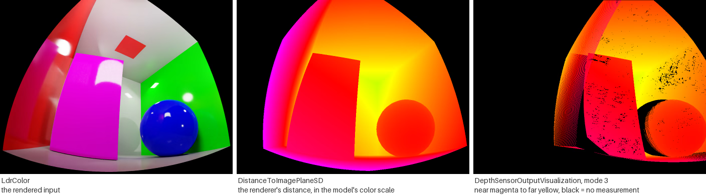
One frame of a Cornell box test scene’s fisheye depth product, three times.
Left, the rendered LdrColor input; center, the renderer’s
DistanceToImagePlaneSD input, displayed with the color
scale of the right panel; right, the model’s
DepthSensorOutputVisualization in mode 3, near surfaces magenta and
red, far ones yellow, no measurement black. The depth image has holes
beside the tall box and the sphere where the second imager would not see
the surface, an empty band along the left edge where that imager would
look past the rendered view, and nothing for the floor nearest the camera,
closer than its near limit. Noise is off, so every missing value comes from
the geometry.#
Features at a glance#
A RenderProduct that renders through a camera, has the model’s API schema applied and requests the three camera outputs the model reads and the five it writes, with several depth products in one step, cameras with different projections and a tiled product (Set Up a Depth Product).
Noise and quantization that move measurements along their image row, and a confidence test that decides which pixels get a measurement at all, each change checked against the model’s own confidence map (Tune Noise, Quantization and Confidence).
A device’s published specification turned into a depth product that behaves like the device, with the datasheet fields and their attributes, the near limit that the maximum disparity and the product width set together, and the unit conversions (Build a Profile from a Spec Sheet).
The inputs and the set of RenderVars the pipeline needs, the stages that produce and discard values, the five outputs with type and shape, what a zero means, the two frames, units and the visualization modes (Outputs).
When to use it#
Use this model when the thing under test is a perception stack that will consume a depth camera’s output, on a robot, a vehicle or a virtual factory floor. Such a system must process occlusion holes, missing measurements on smooth surfaces, quantization that coarsens with distance and noise that changes between frames. The model simulates these effects in a controlled scene. The parameters belong to the Camera prim. To simulate different devices in the same step, use separate Cameras and RenderProducts, with each Camera authoring its own baseline, optics and noise; Set Up a Depth Product shows how, and Build a Profile from a Spec Sheet takes the numbers from a device’s published specification.
What it does not model#
These are by-design limits of the model, not misconfigurations; the Limitations page points here.
Not modeled |
Consequence |
|---|---|
A second render |
There is one rendered view. The second imager exists only as a reprojection of the first, so anything hidden from the rendered view is hidden from both. |
Stereo matching |
No correspondence search is performed and no mismatches are produced. The errors present are the ones these pages describe, occlusion holes, confidence culling, disparity quantization and noise, and not the false matches a real matcher makes on repeating patterns. |
Per-pixel timing |
The model adds no time structure of its own: no output contains a timestamp or a per-pixel time offset, and every pixel of a frame is processed identically. Whatever timing the rendered frame already had, for example from a rolling shutter, is what you have. |
Materials and illumination, physically |
Surface response reaches this model only through the tone-mapped color image, as texture in the confidence test. There is no infrared reflectance, and no material property changes the reported distance. |
Scene units |
No unit conversion is applied to the inputs, so the distance image and the point cloud inherit the units of the outputs they are computed from; Outputs states which unit each one is in. |
Pages under this model#
Use USD Attributes for controls and clamps, and How-To to build and tune a depth product. Read Outputs before mapping images or points: it defines required inputs, invalid values, units and coordinate frames.