

Parameterize One Sensor Two Ways: SICK TiM781#
The SICK TiM781 uses one laser and detector with a rotating mirror. It measures 811 directions over a 270-degree arc at 15 Hz. This tutorial represents that scan in two ways: one rotary emitter sampled at each encoder tick, or 811 explicitly timed solid-state emitters. Both reproduce the nominal directions and timing at 15 Hz.
Choose the rotary profile for a compact configuration that matches the rotating mirror and adjusts firing times automatically when the scan rate changes. Choose the solid-state profile when you need to specify or modify individual directions and firing times explicitly. Its fire-time array must be regenerated when the scan rate changes.
The profiles use public manufacturer documentation. The tables below distinguish published values, derived values, approximations and missing calibration data.
The solid-state profile uses scanType = "SOLID_STATE" to schedule a fixed
list of directions and firing times. The physical TiM781 uses a rotating
mirror; this representation does not model electronic beam steering.
Important
Treat the resulting profiles as documentation-derived baselines. They contain what can be copied or reasonably inferred from the public manuals. Emitter and detector behavior that those sources do not define — including unit-specific optical power, receiver response and thresholds, noise, corrections, and intensity transfer — remains generic or approximate and must be tuned against measured sensor data for higher-fidelity use. Neither profile is a certified digital twin of a particular hardware unit.
Model prerequisites#
Before using this tutorial, read Lidar generic core model for ticks, emitters, channels and returns, and Configure a Firing Pattern for authoring a firing pattern.
Parameterize a Rotary Lidar: Velodyne Alpha Prime shows a rotary profile with multiple emitters per tick.
Source documents#
Three SICK sources, for order number TIM781-2174101 and part number
1096807:
TiM781-2174101 datasheet, accessed July 24, 2026. This is a dynamically generated German datasheet, despite sometimes being described as a manual.
TiM781 operating instructions, document 8024231/1ONO/2024-09-25.
TiM timestamp and index-signal explanation, SICK knowledge article KA-10209, version 1.0.
The short datasheet supplies the product envelope. The operating instructions add the measurement mechanism, telegram encoding, beam data, measurement origin, RSSI behavior, and the timing needed to distinguish a physical encoder shot from an output sample. The knowledge article locates the TiM zero index and scan timestamp at -90 degrees.
Source confidence#
Each mapping below belongs to one of four categories.
Category |
Meaning |
How to use it |
|---|---|---|
Direct |
Source and simulation values have the same physical meaning and units. |
Copy the value, then verify coordinate, boundary, and array conventions. |
Derived |
The source provides enough information to calculate the value. |
Record the equation and source assumptions with the result. |
Approximation |
The source claim and Lidar generic core model have different semantics. |
Use it as an initial condition and validate against measurements. |
Calibration |
Public sources do not define the required value or transfer function. |
Keep a documented starting value and replace it with measured data. |
Read the product-level specifications#
The feature table on page 51 of the operating instructions gives the product envelope this profile is built from: a 15 Hz scanning frequency, a 270-degree aperture angle scanning from -45 to +225 degrees at a nominal 1/3-degree increment, a 0.05 to 25 m working range with 1 mm distance resolution, an 850 nm source, one evaluated echo, and RSSI values from 0 to 254.
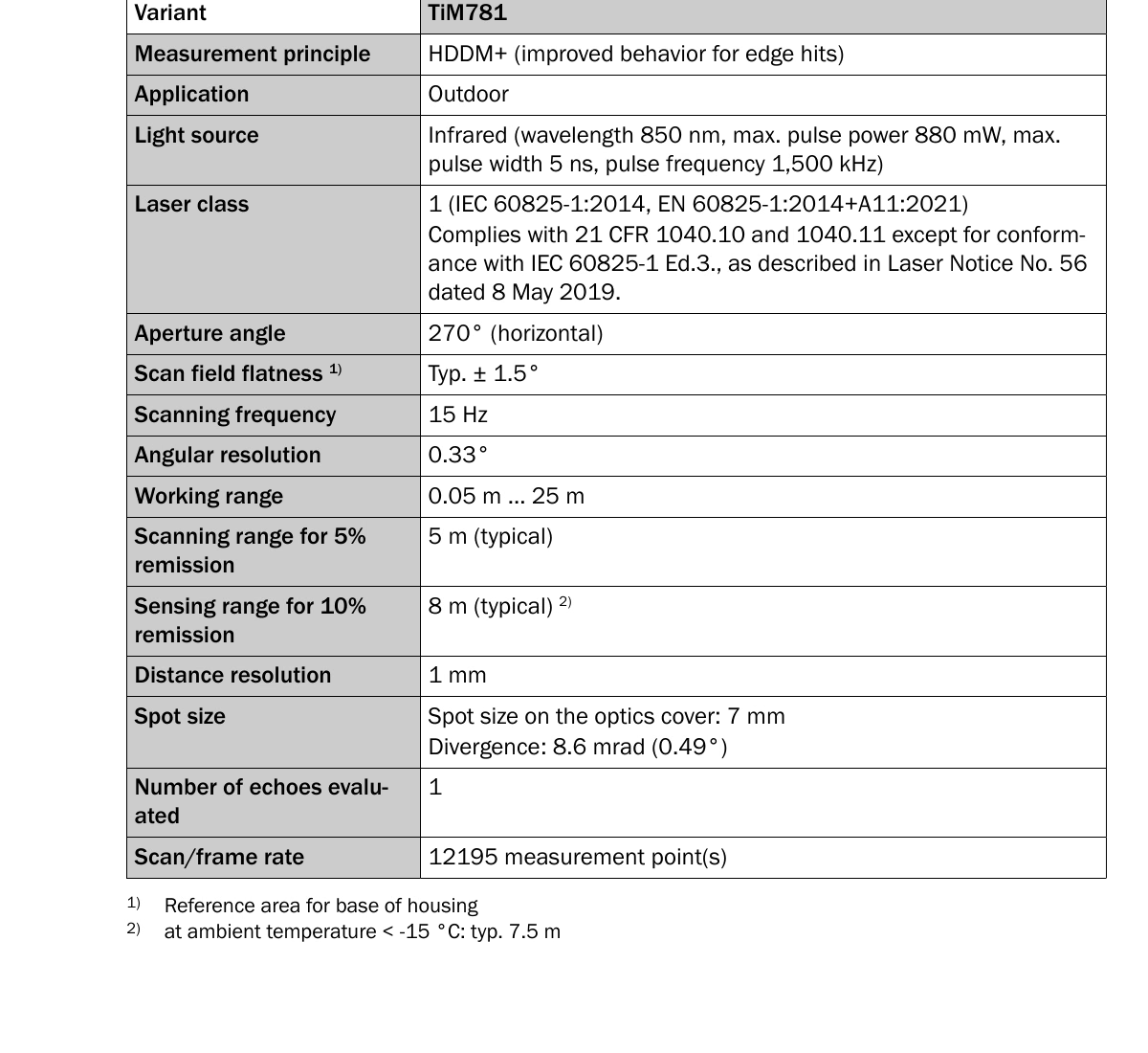
Excerpt from the TiM781 operating instructions, document 8024231/1ONO/2024-09-25, page 51.#
The complete source-to-model mapping is:
Manufacturer information |
Simulation attribute or action |
Value in this profile |
Category |
Notes |
|---|---|---|---|---|
Rotating mirror with encoder-triggered angular increments |
|
|
Approximation |
|
15 Hz scanning frequency |
|
|
Direct |
One scan period takes about 66.667 ms. |
Nominal 1/3-degree encoder step |
Rotary tick step or solid-state azimuth array |
|
Derived |
The telegram encodes the repeating fraction as 0.3333 degrees; the explicit profile derives each angle directly. |
Scan from -45 to +225 degrees |
Rotary valid interval or explicit solid-state azimuth array |
270-degree interval with 811 inclusive directions |
Derived |
Both preserve increasing SICK-angle order; the solid-state frame authors each direction explicitly. |
One planar distance-data channel |
|
Rotary: |
Approximation |
The TiM’s |
0.05-25 m working range |
|
|
Direct |
|
1 mm distance resolution |
|
|
Direct |
This is output granularity, not measurement accuracy. |
Statistical error below 20 mm at 1 sigma |
|
|
Approximation |
The source condition is room temperature, at most 10 m, and 90% remission. |
Systematic error of +/-60 mm |
Validation target |
Not authored as random error |
Approximation |
A signed, condition-dependent bias cannot be inferred from a symmetric bound. |
Typical detection of 10% remission at 8 m |
|
|
Approximation |
The source says typical range, while the model pair describes a detection threshold. The 5%/5 m point remains a second validation target. |
850 nm source |
|
|
Direct |
This affects spectral material response and photon conversion. |
Up to 880 mW and up to 5 ns |
|
|
Direct |
They are not nominal calibrated operating values. |
8.6 mrad single-pulse divergence and 5.8 mrad HDDM scan-width supplement |
|
|
Approximation |
The horizontal value represents the aggregate measurement footprint. |
One evaluated echo |
|
|
Direct |
No multi-return capacity is needed. |
Nonlinear, uncalibrated RSSI from 0 to 254 |
Intensity scale and calibration work |
|
Calibration |
This reports 0–2.54. Matching the device’s 0–254 RSSI requires calibrated scaling and a nonlinear transfer curve. |
Measurement plane 62.46 mm above the housing-base reference |
|
|
Derived |
The rotary array has one value and the solid-state array repeats it 811 times; the mounting asset must establish X/Y. |
Build the profile#
Start with an OmniLidar prim and apply the generic core API. The model
metadata selects NVIDIA’s configurable model, while marketName identifies
this product parameterization — refer to
model identity for what that
combination does and does not resolve.
#usda 1.0

def OmniLidar "SICK_TiM781" (
    prepend apiSchemas = ["OmniSensorGenericLidarCoreAPI"]
)
{
    string omni:sensor:modelName = "LidarCore"
    string omni:sensor:modelVersion = "0"
    string omni:sensor:modelVendor = "NVIDIA"
    string omni:sensor:marketName = "SICK TiM781-2174101"
    double2 omni:sensor:frameRate = (15, 1)
}
from pxr import Gf, Sdf

lidar = stage.DefinePrim("/SICK_TiM781", "OmniLidar")
lidar.AddAppliedSchema("OmniSensorGenericLidarCoreAPI")
lidar.CreateAttribute("omni:sensor:modelName", Sdf.ValueTypeNames.String, custom=False).Set(
    "LidarCore"
)
lidar.CreateAttribute("omni:sensor:modelVersion", Sdf.ValueTypeNames.String, custom=False).Set(
    "0"
)
lidar.CreateAttribute("omni:sensor:modelVendor", Sdf.ValueTypeNames.String, custom=False).Set(
    "NVIDIA"
)
lidar.CreateAttribute("omni:sensor:marketName", Sdf.ValueTypeNames.String, custom=False).Set(
    "SICK TiM781-2174101"
)
lidar.CreateAttribute("omni:sensor:frameRate", Sdf.ValueTypeNames.Double2, custom=False).Set(
    Gf.Vec2d(15.0, 1.0)
)
Choose the scan representation#
The operating instructions describe the mechanism on page 14: a rotating mirror sweeps the beam, and each output measurement combines multiple pulses taken at an encoder-triggered angular increment.
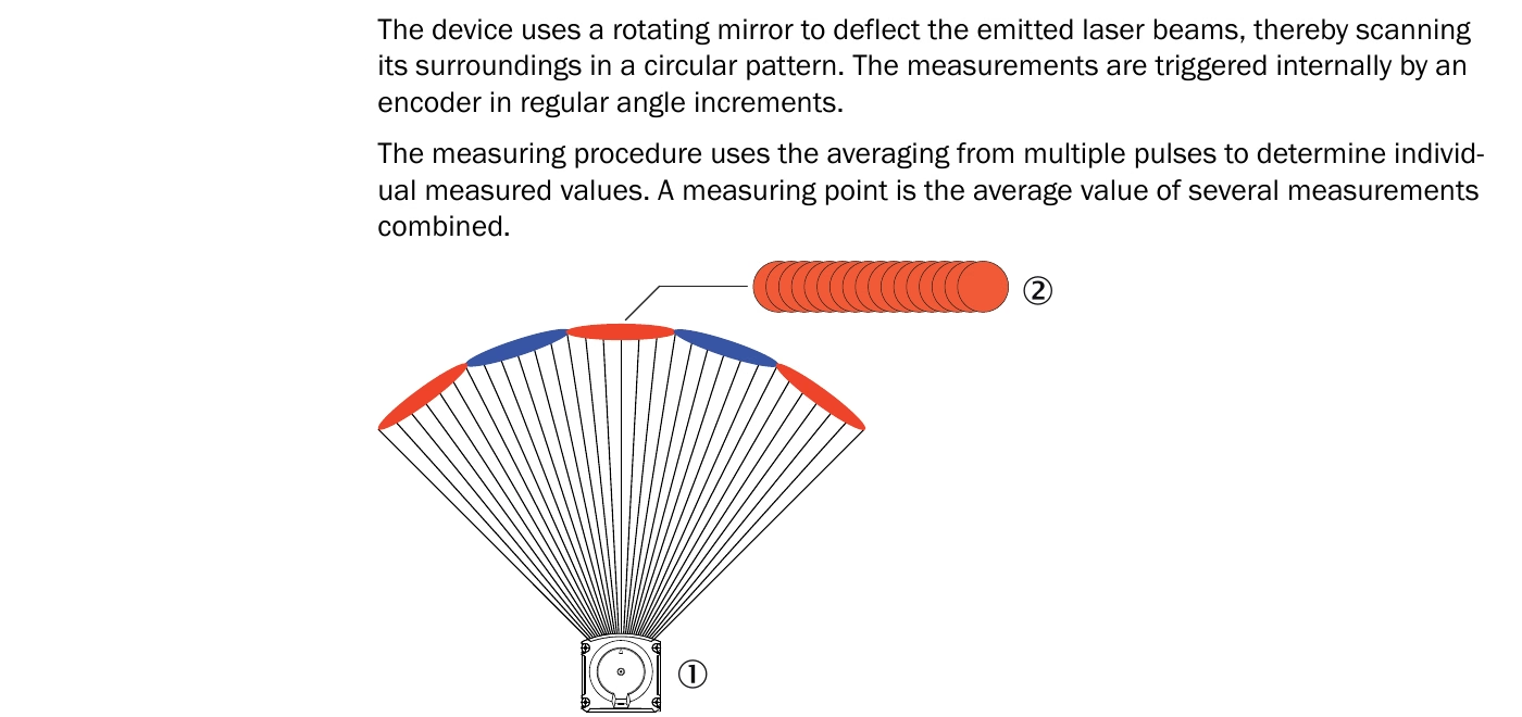
Excerpt from the TiM781 operating instructions, document 8024231/1ONO/2024-09-25, page 14.#
Choose a representation according to the required scheduling behavior:
Representation |
Core structure |
What it preserves |
Prefer it when |
|---|---|---|---|
Rotary mechanism |
One emitter reused at 1080 candidate ticks per rotation; the visible field retains ticks 135 through 945 |
Persistent absolute rotary-scheduler phase across calls, zero-index alignment, scan-rate-derived cadence, and 811 visible samples |
Mechanism fidelity, compact configuration, or changing scan rate matters |
Explicit solid-state frame |
811 virtual emitters in one line, each with an explicit direction and fire time |
The same 811 directions and per-ray offsets at 15 Hz, each scan completed at the 66.667 ms period boundary |
A fixed ray layout is needed and the scan rate stays at 15 Hz |
Use the rotary profile to derive shot timing from scan rate. Use the solid-state profile when the application needs an explicit list of directions and firing times at 15 Hz. With partial outputs, both profiles deliver the portion of the scan covered by each render step.
Rotary representation#
The rotary profile models the documented mechanism directly:
#usda 1.0

def OmniLidar "SICK_TiM781"
{
    token omni:sensor:Core:scanType = "ROTARY"
    token omni:sensor:Core:rotationDirection = "CCW"
    float omni:sensor:Core:rotPatternFiringResDeg = 0.3333333
    uint omni:sensor:Core:numberOfEmitters = 1
    uint omni:sensor:Core:numberOfChannels = 1
}
from pxr import Gf, Sdf

lidar = stage.DefinePrim("/SICK_TiM781", "OmniLidar")
lidar.CreateAttribute("omni:sensor:Core:scanType", Sdf.ValueTypeNames.Token, custom=False).Set(
    "ROTARY"
)
lidar.CreateAttribute(
    "omni:sensor:Core:rotationDirection", Sdf.ValueTypeNames.Token, custom=False
).Set("CCW")
lidar.CreateAttribute(
    "omni:sensor:Core:rotPatternFiringResDeg", Sdf.ValueTypeNames.Float, custom=False
).Set(0.3333333)
lidar.CreateAttribute(
    "omni:sensor:Core:numberOfEmitters", Sdf.ValueTypeNames.UInt, custom=False
).Set(1)
lidar.CreateAttribute(
    "omni:sensor:Core:numberOfChannels", Sdf.ValueTypeNames.UInt, custom=False
).Set(1)
rotationDirection describes the simulated beam sweep after coordinate
conversion. It is not a claim about the mechanical mirror-shaft direction, which
the source does not name.
The schema marks rotationDirection and rotPatternFiringResDeg as
rotary-only. Do not author the solid-state-only numLines,
numRaysPerLine, or emitterState:*:bank attributes in the rotary profile.
Not every attribute without such a marking acts on both scan types, though: the
valid-azimuth window and startAzimuthOffsetDeg, for example, act on rotary
sensors only.
Solid-state representation#
The alternative profile authors the observable sweep as one explicit frame:
#usda 1.0

def OmniLidar "SICK_TiM781_SolidState"
{
    token omni:sensor:Core:scanType = "SOLID_STATE"
    uint omni:sensor:Core:numberOfEmitters = 811
    uint omni:sensor:Core:numberOfChannels = 811
    uint omni:sensor:Core:numLines = 1
    uint[] omni:sensor:Core:numRaysPerLine = [811]
}
from pxr import Gf, Sdf

lidar = stage.DefinePrim("/SICK_TiM781_SolidState", "OmniLidar")
lidar.CreateAttribute("omni:sensor:Core:scanType", Sdf.ValueTypeNames.Token, custom=False).Set(
    "SOLID_STATE"
)
lidar.CreateAttribute(
    "omni:sensor:Core:numberOfEmitters", Sdf.ValueTypeNames.UInt, custom=False
).Set(811)
lidar.CreateAttribute(
    "omni:sensor:Core:numberOfChannels", Sdf.ValueTypeNames.UInt, custom=False
).Set(811)
lidar.CreateAttribute("omni:sensor:Core:numLines", Sdf.ValueTypeNames.UInt, custom=False).Set(1)
lidar.CreateAttribute(
    "omni:sensor:Core:numRaysPerLine", Sdf.ValueTypeNames.UIntArray, custom=False
).Set([811])
The solid-state representation allocates 811 channel slots, one per explicit
emitter. These represent angular samples from the device’s single physical
detector. Storage is sized by numberOfChannels and indexed by EmitterId.
The profile authors channelId values from 1 through 811, equal to
EmitterId + 1. The output reports these labels unchanged.
The solid-state profile leaves startAzimuthOffsetDeg and the valid-azimuth
attributes unauthored, because neither steers nor clips a solid-state sensor’s
rays. The directions and scan window are already encoded in the emitter arrays — as
the azimuth window notes, a solid-state
sensor takes its angular extent from the emitter arrays instead.
Derive the shared scan timing#
Page 79 of the operating instructions specifies a 15 Hz scan frequency, a nominal 1/3-degree angular increment, and the
16.2 kHz measurement frequency the telegram derives from them. The same page
identifies one distance-data channel, DIST1.
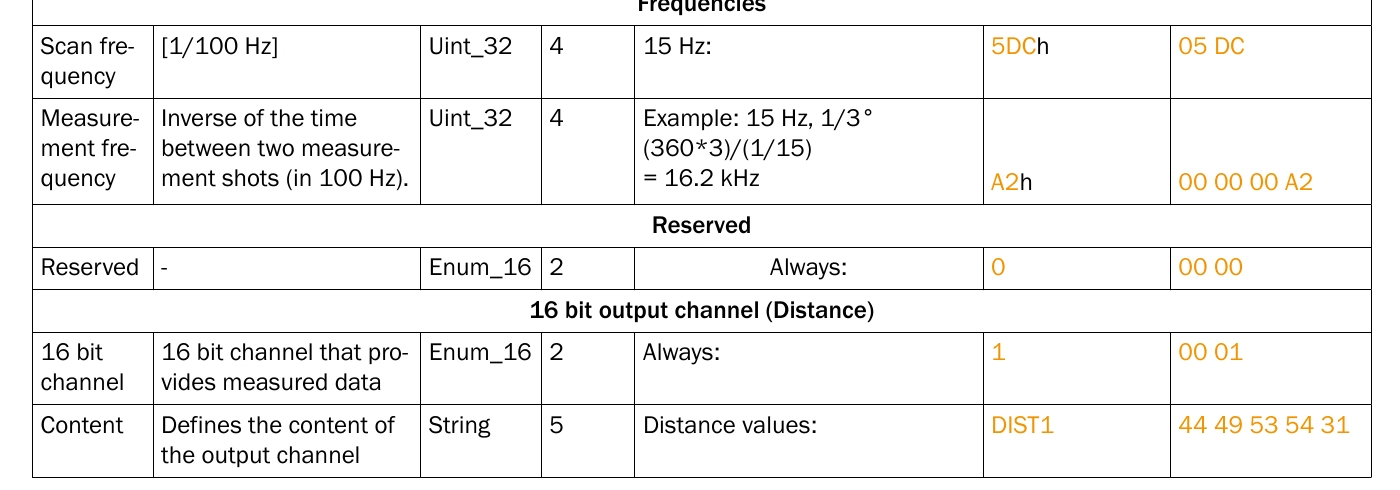
Excerpt from the TiM781 operating instructions, document 8024231/1ONO/2024-09-25, page 79.#
full_rotation_ticks = 360 / (1 / 3) = 1080
rotation_period = 1 / 15 = 66.6667 ms
tick_period = 1 / 16200 = 61.7284 us
visible_sweep_time = 810 * tick_period = 50 ms
blind_sector_time = 66.6667 ms - 50 ms = 16.6667 ms
There are 810 intervals and 811 inclusive angular bins from -45 to +225 degrees.
The telegram represents the repeating 1/3-degree value in units of 1/10000
degree as 3333, or 0.3333 degrees. The rotary profile uses the nominal
encoder interpretation, approximately 360 / 1080, so the core snaps the
schedule to 1080 ticks per rotation rather than treating the telegram’s
quantized decimal as a phase-slipping physical step. Because 1/3 degree divides
360 exactly, this is the case where a rotation does hold a fixed number of ticks
— refer to fractional ticks for what
happens when the angular step does not divide 360.
The explicit solid-state profile derives each direction and timestamp from the
same nominal encoder sequence. For i = 0 .. 810:
sick_angle[i] = -45 + i / 3 degrees
authored_core_azimuth[i] = 45 - i / 3 degrees
fireTimeNs[i] = round((135 + i) * 1e9 / 16200)
Use absolute rounding as shown, rather than repeatedly adding a rounded tick period. The first and last fire times are 8,333,333 ns and 58,333,333 ns, and each of the 810 adjacent intervals is either 61,728 ns or 61,729 ns (490 and 320 of them respectively). The approximately 16.667 ms gap from the last visible point to the next frame’s first visible point represents the 90-degree blind sector.
The explicit pattern is tied to 15 Hz. If the simulated scan rate changes, regenerate its fire-time array. The rotary scheduler derives its cadence from the scan rate automatically, which is the main reason to prefer it when the rate is not fixed.
Configure the rotary frame and visible sector#
SICK telegram samples run from -45 toward +225 degrees in positive increments. The scan timestamp is captured earlier, at the mirror’s -90-degree zero index. The generic core converts its authored azimuth to the right-handed Cartesian ray direction.
Figure 1 on page 11 locates the scan plane 62.46 mm above the housing-base reference and shows the -45 through +225-degree sector.
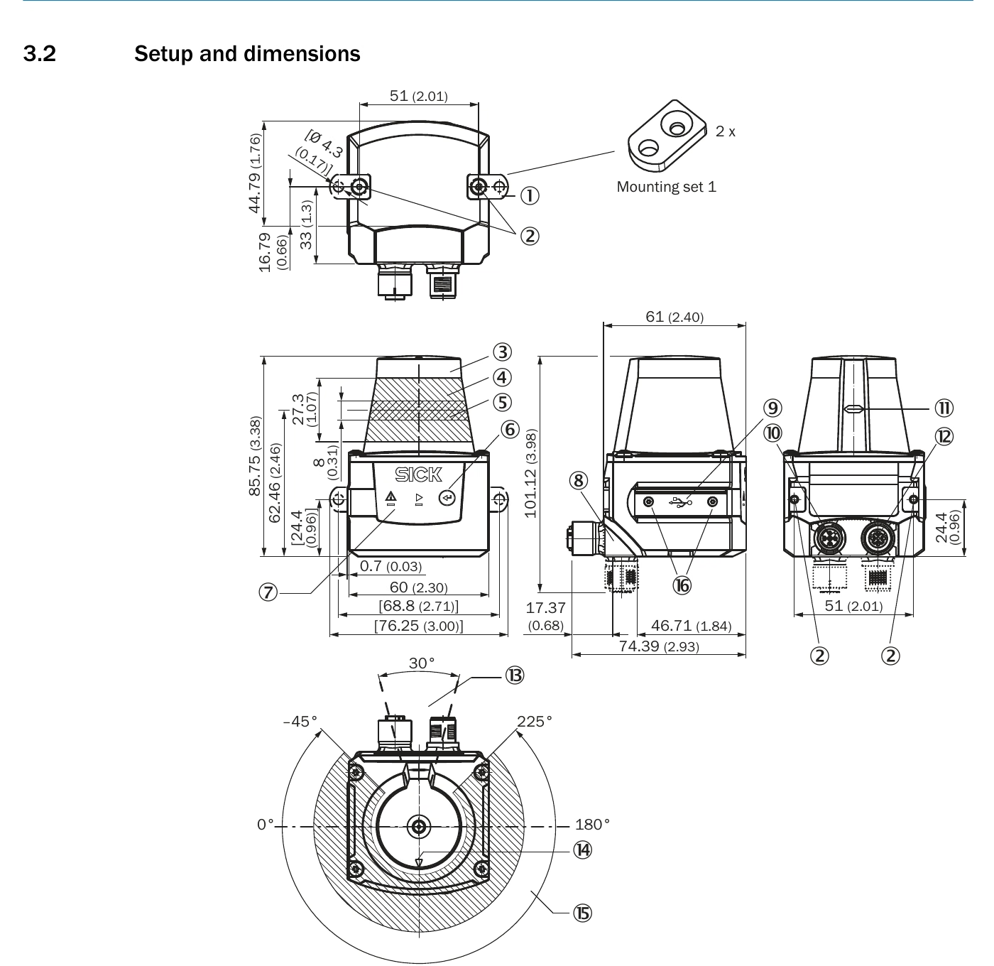
Figure 1 from the TiM781 operating instructions, document 8024231/1ONO/2024-09-25, page 11.#
The rotary profile uses:
#usda 1.0

def OmniLidar "SICK_TiM781"
{
    token omni:sensor:Core:rotationDirection = "CCW"
    float omni:sensor:Core:startAzimuthOffsetDeg = 90.0
    float omni:sensor:Core:validStartAzimuthDeg = 44.9999
    float omni:sensor:Core:validEndAzimuthDeg = 315.0001
}
from pxr import Gf, Sdf

lidar = stage.DefinePrim("/SICK_TiM781", "OmniLidar")
lidar.CreateAttribute(
    "omni:sensor:Core:rotationDirection", Sdf.ValueTypeNames.Token, custom=False
).Set("CCW")
lidar.CreateAttribute(
    "omni:sensor:Core:startAzimuthOffsetDeg", Sdf.ValueTypeNames.Float, custom=False
).Set(90.0)
lidar.CreateAttribute(
    "omni:sensor:Core:validStartAzimuthDeg", Sdf.ValueTypeNames.Float, custom=False
).Set(44.9999)
lidar.CreateAttribute(
    "omni:sensor:Core:validEndAzimuthDeg", Sdf.ValueTypeNames.Float, custom=False
).Set(315.0001)
At tick 0, the offset maps to the SICK -90-degree zero index and no visible ray is produced. Tick 135, about 8.333 ms later, is the first visible ray at -45 degrees. Tick 945, about 58.333 ms after the timestamp, is the last visible ray at approximately +225 degrees. The nominal internal valid interval is 45 through 315 degrees; the excluded sector splits the 16.667 ms blind time around the visible output.
These are nominal offsets. SICK specifies a +/-300 us tolerance for the timestamp taken at the zero index. Generic-core firing timestamps can additionally be displaced by less than one rotary tick, about 61.728 us here, because firing timestamps remain relative to the render-frame start rather than carrying an exact fractional absolute tick phase.
The azimuth bounds are authored 0.0001 degree outside the nominal 45 and 315 degrees, so the window is slightly wider than the nominal 270-degree interval.
Define the emitter arrays#
The rotary profile applies one emitter pattern at every tick:
#usda 1.0

def OmniLidar "SICK_TiM781"
{
    float[] omni:sensor:Core:emitterState:s001:azimuthDeg = [0.0]
    float[] omni:sensor:Core:emitterState:s001:elevationDeg = [0.0]
    float[] omni:sensor:Core:emitterState:s001:vertOffsetM = [0.06246]
    uint[] omni:sensor:Core:emitterState:s001:fireTimeNs = [0]
    uint[] omni:sensor:Core:emitterState:s001:channelId = [1]
    uint[] omni:sensor:Core:emitterState:s001:rangeId = [0]
}
from pxr import Gf, Sdf

lidar = stage.DefinePrim("/SICK_TiM781", "OmniLidar")
lidar.CreateAttribute(
    "omni:sensor:Core:emitterState:s001:azimuthDeg", Sdf.ValueTypeNames.FloatArray, custom=False
).Set([0.0])
lidar.CreateAttribute(
    "omni:sensor:Core:emitterState:s001:elevationDeg",
    Sdf.ValueTypeNames.FloatArray,
    custom=False,
).Set([0.0])
lidar.CreateAttribute(
    "omni:sensor:Core:emitterState:s001:vertOffsetM",
    Sdf.ValueTypeNames.FloatArray,
    custom=False,
).Set([0.06246])
lidar.CreateAttribute(
    "omni:sensor:Core:emitterState:s001:fireTimeNs", Sdf.ValueTypeNames.UIntArray, custom=False
).Set([0])
lidar.CreateAttribute(
    "omni:sensor:Core:emitterState:s001:channelId", Sdf.ValueTypeNames.UIntArray, custom=False
).Set([1])
lidar.CreateAttribute(
    "omni:sensor:Core:emitterState:s001:rangeId", Sdf.ValueTypeNames.UIntArray, custom=False
).Set([0])
The SICK telegram’s DIST1 is one distance-data channel; the measurements
within it are angular samples, not separate detector channels. The point cloud
reports the authored channelId unchanged, so every point carries
ChannelId 1 — refer to channel ids.
The explicit solid-state profile stores all 811 ray slots in one emitter state:
# i = 0 .. 810; the authored profile expands every array.
azimuthDeg[i] = 45 - i / 3
elevationDeg[i] = 0
vertOffsetM[i] = 0.06246
fireTimeNs[i] = round((135 + i) * 1e9 / 16200)
channelId[i] = i + 1
rangeId[i] = 0
bank[i] = 0
The resulting ChannelId ranges from 1 through 811 and EmitterId from 0
through 810. This is a synthetic sample-slot identity; the physical telegram
still contains one distance-data channel, DIST1.
The vertical offset assumes the prim origin is on the housing-base reference plane and maps only the Z separation to the optical plane. It is authored once in the rotary profile and repeated for all 811 explicit emitters in the solid-state profile. The source dimension does not by itself establish the prim’s lateral origin; the housing or mounting asset must define X/Y. If a mounting asset already places the prim at the marked optical origin, remove the emitter offset rather than applying the translation twice.
Configure range and error#
Both profiles use the following range limits, error scale and threshold calibration:
#usda 1.0

def OmniLidar "SICK_TiM781"
{
    float omni:sensor:Core:nearRangeM = 0.05
    float omni:sensor:Core:farRangeM = 25.0
    float omni:sensor:Core:rangeResolutionM = 0.001
    float omni:sensor:Core:rangeAccuracyM = 0.02
    float omni:sensor:Core:minReflectance = 0.10
    float omni:sensor:Core:minReflectionRangeM = 8.0
    uint omni:sensor:Core:maxReturns = 1
    uint omni:sensor:Core:rangeCount = 1
    float[] omni:sensor:Core:rangesMinM = [0.05]
    float[] omni:sensor:Core:rangesMaxM = [25.0]
}
from pxr import Gf, Sdf

lidar = stage.DefinePrim("/SICK_TiM781", "OmniLidar")
lidar.CreateAttribute(
    "omni:sensor:Core:nearRangeM", Sdf.ValueTypeNames.Float, custom=False
).Set(0.05)
lidar.CreateAttribute("omni:sensor:Core:farRangeM", Sdf.ValueTypeNames.Float, custom=False).Set(
    25.0
)
lidar.CreateAttribute(
    "omni:sensor:Core:rangeResolutionM", Sdf.ValueTypeNames.Float, custom=False
).Set(0.001)
lidar.CreateAttribute(
    "omni:sensor:Core:rangeAccuracyM", Sdf.ValueTypeNames.Float, custom=False
).Set(0.02)
lidar.CreateAttribute(
    "omni:sensor:Core:minReflectance", Sdf.ValueTypeNames.Float, custom=False
).Set(0.1)
lidar.CreateAttribute(
    "omni:sensor:Core:minReflectionRangeM", Sdf.ValueTypeNames.Float, custom=False
).Set(8.0)
lidar.CreateAttribute("omni:sensor:Core:maxReturns", Sdf.ValueTypeNames.UInt, custom=False).Set(
    1
)
lidar.CreateAttribute("omni:sensor:Core:rangeCount", Sdf.ValueTypeNames.UInt, custom=False).Set(
    1
)
lidar.CreateAttribute(
    "omni:sensor:Core:rangesMinM", Sdf.ValueTypeNames.FloatArray, custom=False
).Set([0.05])
lidar.CreateAttribute(
    "omni:sensor:Core:rangesMaxM", Sdf.ValueTypeNames.FloatArray, custom=False
).Set([25.0])
rangeOffsetM is intentionally not set to 0.05 m. It makes nearby geometry
invisible to avoid self-occlusion; nearRangeM is the attribute that
represents the published minimum working range.
The 1 mm value is the reported distance increment. It does not force internal floating-point point cloud coordinates to be quantized — that distinction is accuracy versus resolution. The 20 mm value is a conservative approximation for the published statistical error, not a representation of the separate +/-60 mm systematic bound. Fit systematic bias with measured residuals rather than turning it into zero-mean random noise.
Configure beam and intensity behavior#
The following settings approximate the aggregate beam footprint and retain a linear starting intensity map:
#usda 1.0

def OmniLidar "SICK_TiM781"
{
    token omni:sensor:Core:rayType = "IDEALIZED"
    float omni:sensor:Core:waveLengthNm = 850.0
    float omni:sensor:Core:divergenceHorDeg = 0.8251
    float omni:sensor:Core:divergenceVerDeg = 0.4927
    float omni:sensor:Core:peakPowerW = 0.88
    uint omni:sensor:Core:pulseTimeNs = 5
    token omni:sensor:Core:intensityProcessing = "NORMALIZATION"
    token omni:sensor:Core:intensityMappingType = "LINEAR"
    float omni:sensor:Core:intensityScalePercent = 254.0
}
from pxr import Gf, Sdf

lidar = stage.DefinePrim("/SICK_TiM781", "OmniLidar")
lidar.CreateAttribute("omni:sensor:Core:rayType", Sdf.ValueTypeNames.Token, custom=False).Set(
    "IDEALIZED"
)
lidar.CreateAttribute(
    "omni:sensor:Core:waveLengthNm", Sdf.ValueTypeNames.Float, custom=False
).Set(850.0)
lidar.CreateAttribute(
    "omni:sensor:Core:divergenceHorDeg", Sdf.ValueTypeNames.Float, custom=False
).Set(0.8251)
lidar.CreateAttribute(
    "omni:sensor:Core:divergenceVerDeg", Sdf.ValueTypeNames.Float, custom=False
).Set(0.4927)
lidar.CreateAttribute(
    "omni:sensor:Core:peakPowerW", Sdf.ValueTypeNames.Float, custom=False
).Set(0.88)
lidar.CreateAttribute(
    "omni:sensor:Core:pulseTimeNs", Sdf.ValueTypeNames.UInt, custom=False
).Set(5)
lidar.CreateAttribute(
    "omni:sensor:Core:intensityProcessing", Sdf.ValueTypeNames.Token, custom=False
).Set("NORMALIZATION")
lidar.CreateAttribute(
    "omni:sensor:Core:intensityMappingType", Sdf.ValueTypeNames.Token, custom=False
).Set("LINEAR")
lidar.CreateAttribute(
    "omni:sensor:Core:intensityScalePercent", Sdf.ValueTypeNames.Float, custom=False
).Set(254.0)
Figure 4 on page 15 of the operating instructions gives the beam expansion and the light-spot calculation for an HDDM measurement: 8.6 mrad single-pulse divergence, plus a 5.8 mrad supplement in the scan direction when the footprint of a complete measurement is calculated. The profile converts the aggregate 14.4 mrad horizontal and 8.6 mrad vertical footprints to degrees.
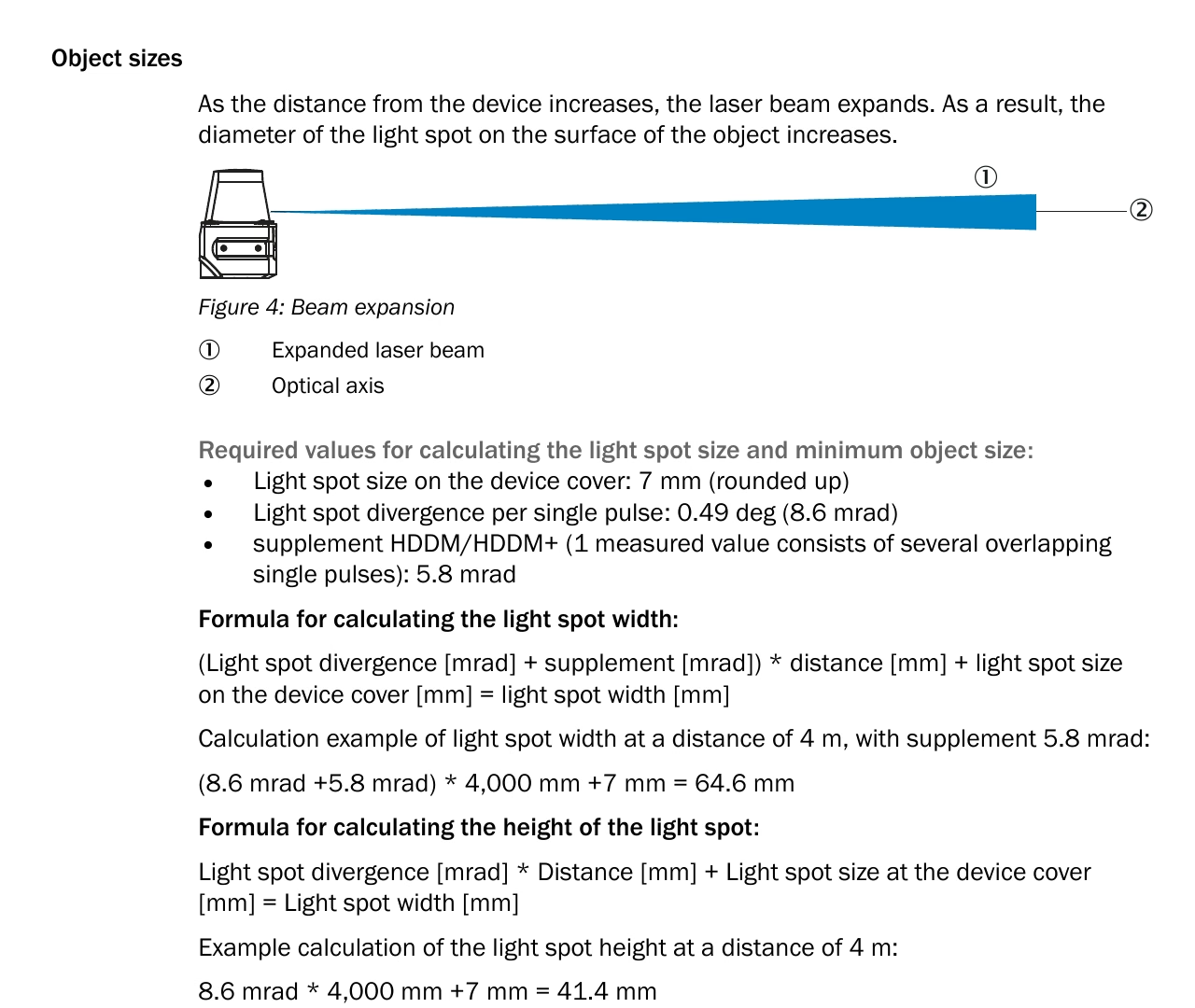
Figure 4 and its light-spot calculation from the TiM781 operating instructions, document 8024231/1ONO/2024-09-25, page 15.#
This is an approximation because the generic model does not average the sensor’s sequence of 1.5 MHz sub-pulses.
Divergence participates in radiometric calculations with the default
IDEALIZED ray type, so start with that lower-cost representation. Use
GAUSSIAN_BEAM only when geometric footprint and partial-hit fidelity are
required and validated; it traces multiple rays and has a substantial
performance cost. Tune Intensity and Point Drops covers the choice.
The published 880 mW and 5 ns values are maxima. They are source-based starting points, but they remain calibration inputs rather than nominal unit measurements.
The linear intensity map is a placeholder, and RSSI fidelity cannot be claimed until it is replaced. Page 19 of the operating instructions states that SICK RSSI is nonlinear and uncalibrated, and affected by remission, range, incidence angle, ambient light, temperature, and unit variation.
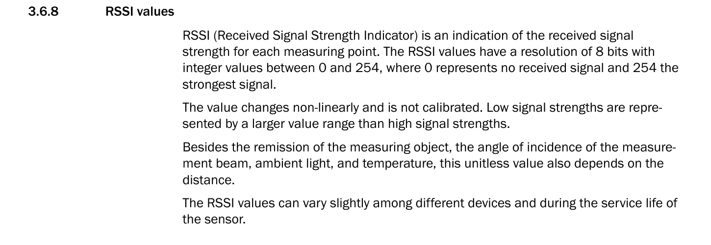
Excerpt from the TiM781 operating instructions, document 8024231/1ONO/2024-09-25, page 19.#
The profile retains intensityScalePercent = 254 with linear mapping,
which reports 0–2.54. Matching the device’s 0–254 RSSI requires calibrated
scaling and a nonlinear encoding curve fitted from paired sensor and
simulation captures. NORMALIZATION alone does not reproduce the transfer
function.
Parameter mapping and calibration#
Direct and derived parameters#
The public documents support the following without unit-specific calibration:
15 Hz rate, nominal encoder cadence, visible sector, and blind-sector timing, represented either by rotary scheduling or an explicit frame;
one planar physical distance channel and one echo; the modeled emitter and channel counts depend on the selected scheduler;
minimum and maximum range, millimeter output resolution, wavelength, and the 10%/8 m detection anchor;
source-based optical maxima, nominal divergence, and the measurement-plane location;
RSSI range and the fact that the published RSSI mapping is nonlinear and uncalibrated.
Approximated parameters#
Published behavior |
Model or source limitation |
Recommended treatment |
|---|---|---|
12,195 measurement points per second |
At 15 Hz this implies 813 points per scan, while -45 to +225 at nominal 1/3-degree increments gives 811 inclusive bins |
Keep the documented geometry in this profile and verify the actual telegram count and outer angles on hardware. |
Telegram step 0.3333 degrees |
The telegram cannot exactly encode the stated repeating 1/3-degree encoder step |
Use 1080 ticks per rotation; use a captured scan to determine whether firmware introduces any phase or boundary variation. |
Statistical error below 20 mm and systematic error +/-60 mm |
|
Use 0.02 m as a statistical starting scale and fit signed bias separately. |
8.6 mrad pulse divergence plus HDDM scan-width supplement |
One generic beam cannot reproduce multi-pulse averaging |
Use the aggregate footprint as an approximation and validate small-object and edge-hit behavior. |
5%/5 m and 10%/8 m detection points |
The generic model has one threshold anchor |
Use 10%/8 m as the profile anchor and retain 5%/5 m as an independent validation point. |
Nonlinear 0-254 RSSI |
No public transfer curve is supplied |
Fit intensity mapping from calibrated remission targets across range and incidence angle. |
Typical scan-field flatness of +/-1.5 degrees |
Flatness is a systematic shape tolerance, not a random elevation distribution |
Keep angular jitter at zero until a measured scan-plane correction or distribution is available. |
Parameters requiring calibration#
The documents do not uniquely define detector aperture and efficiency, intensity gain, the exact RSSI curve, per-unit angular and distance corrections, random angular-error distributions, temperature-dependent bias, or the nominal values behind the published optical maxima. Measure those terms on the target unit.
The real device can apply edge, particle, median, and averaging filters. These alter or suppress measurements and cannot be reconstructed from already filtered output. Match the device filter configuration before comparing captures with an unfiltered generic-core profile, or reproduce the selected filtering in post-processing.
Unmodeled device properties#
Supply voltage, power consumption, enclosure protection, operating temperature, Ethernet and USB transport, field evaluation, digital I/O, and filter configuration are useful integration requirements but are not generic lidar core parameters. Represent physical housing geometry in mounting, visual, and collision assets, and represent transport or perception filtering in their corresponding systems.
Use the profile#
Save whichever profile you built as its own layer — for example
SICK_TiM781.usda for the rotary mechanism
representation and
SICK_TiM781_SolidState.usda for the
explicit solid-state frame — and
reference it from the scene. This example references the rotary profile’s
default prim:
#usda 1.0

(
    defaultPrim = "World"
    metersPerUnit = 1
    upAxis = "Z"
)

def Xform "World"
{
    over "TiM781" (
        prepend references = @./SICK_TiM781.usda@
    )
    {
        double3 xformOp:translate = (0, 0, 0.5)
        uniform token[] xformOpOrder = ["xformOp:translate"]
    }
}
from pxr import Gf, Sdf

stage.SetMetadata("upAxis", "Z")
stage.SetMetadata("defaultPrim", "World")
stage.SetMetadata("metersPerUnit", 1.0)
world = stage.DefinePrim("/World", "Xform")

ti_m781 = stage.OverridePrim("/World/TiM781")
# Reference the profile default prim; keep the profile beside this layer.
ti_m781.GetReferences().AddReference("./SICK_TiM781.usda")
ti_m781.CreateAttribute("xformOp:translate", Sdf.ValueTypeNames.Double3, custom=False).Set(
    Gf.Vec3d(0.0, 0.0, 0.5)
)
ti_m781.CreateAttribute(
    "xformOpOrder",
    Sdf.ValueTypeNames.TokenArray,
    custom=False,
    variability=Sdf.VariabilityUniform,
).Set(["xformOp:translate"])
To use the explicit profile, reference SICK_TiM781_SolidState.usda.
Its default prim is /SICK_TiM781_SolidState.
Each profile carries a RenderProduct that requests PointCloud; trim its
channels to the ones you consume.
Output Configuration covers the prim-and-RenderProduct pairing and
Outputs the channel names.
partialOutputs = false matches the real sensor’s complete-scan telegram more
closely by withholding output until a modeled scan is complete; a step that
lands mid-scan then delivers
no points, which is not an error. Use
partial output only when render-frame chunks are required by the application.
The rotary profile schedules 811 directions across the -45 to +225 degree
sweep, with nominal TimeOffsetNs from approximately 8.333 to 58.333 ms after
the -90-degree scan timestamp. These profiles leave includeInvalidPoints
false, so misses and rejected returns are omitted: a completed scan carries
up to 811 valid returns. With partialOutputs = true, those returns are
delivered across the steps covering the scan instead.
The solid-state scan completes when a step reaches the 66.667 ms period
boundary, even though the last emitter fires at about 58.333 ms. With
partialOutputs = false, a step ending in the blind gap returns no scan;
the completing step returns it whole.
Each ray fires in the window containing its fire time, with the window’s start included and end excluded. A step entirely inside the blind gap fires no rays. See Configure a Firing Pattern for boundary rules.
For moving sensors or targets, motion BVH must be enabled at the renderer level
as well: the sensor’s own compensation state does not turn it on, and the two
are configured independently — refer to
both settings and Motion Artifacts. The
default NONCOMPENSATED output is raw scan data with motion effects, similar
to a real sensor. COMPENSATED applies the motion-compensation step commonly
performed near the beginning of perception stacks, and is especially important
for mapping.
Validate the profile#
Parameter validation#
Install the introspection package as described in Sensor Definition Validation.
Run parameter and scheduler validation as described in
Sensor Definition Validation for both
/SICK_TiM781 and /SICK_TiM781_SolidState in their respective layers.
Validate each profile separately because their scheduler parameters differ.
For the solid-state profile, also check that numberOfEmitters and
numberOfChannels are 811 and the authored channelId array is 1 through
811. This is the profile’s labeling convention, not a requirement that
channel labels be consecutive.
Geometry and timing checks#
Use a simple static scene first.
Check |
Test setup |
Expected result |
|---|---|---|
Coordinate orientation |
Place narrow targets at SICK angles -45, 0, 90, 180, and 225 degrees |
For both profiles, the first visible sample is -45 degrees and samples proceed toward +225 degrees. |
Scan rate |
Run with a stable simulation clock for several seconds |
15 complete scans per second; the rotary representation also completes 15 modeled rotations per second. |
Encoder cadence |
Inspect rotary candidate ticks or differences between solid-state
|
Rotary: 1080 ticks per rotation. Solid state: 811 explicit ray slots. Both use approximately 61.728 us between adjacent visible samples. |
Visible timing |
Inspect |
Both nominal schedules span approximately 8.333-58.333 ms relative to the assumed -90-degree scan timestamp. The source permits +/-300 us at the index; the rotary core can add less than one modeled tick of displacement. |
Output completion |
Compare scan-ready status with the nominal 66.667 ms period boundary |
Both profiles complete a scan on the step that reaches the 66.667 ms period boundary, which for the rotary profile is the rotation boundary. The solid-state profile completes there too, although its last ray, emitter 810, fires at about 58.333 ms. |
Point count |
Count output angular bins in a surrounding wall scene |
811 bins for either profile’s inclusive -45 to +225 interpretation; compare this with a real telegram because the published 12,195 points/s claim implies 813. |
Channel identity |
Request |
Rotary: every point is channel 1. Solid state: channel IDs 1-811 correspond to the explicit ray slots. |
Emitter identity |
Request |
Rotary: every point is emitter 0. Solid state: emitter IDs 0-810 correspond to the explicit ray slots. |
Measurement origin |
Place a surveyed wall and compare mounting-base and optical-plane transforms |
Rays originate 62.46 mm above a prim placed at the assumed housing base. |
Reading the returns back, and telling a valid entry from an invalid one, is described in Outputs.
Range and intensity checks#
Use surveyed, flat targets.
Verify rejection beyond 25 m, and below 0.4 m rather than 0.05 m: a firing’s first return must also lie at least
minDistBetweenEchosMaway, and neither profile authors that attribute, so its 0.4 m default applies. WithmaxReturns = 1it separates no echoes, so authoring it as0.05restores the published 0.05 m near limit.Compare mean bias and residual spread at several ranges rather than treating +/-60 mm as a Gaussian sigma.
Check a 10% remission target at 8 m and retain 5% at 5 m as a second target.
Confirm one echo for partial occlusions and layered geometry.
Compare 0-254 RSSI distributions over remission, range, and incidence angle; replace the linear map only after collecting enough paired data.
Test narrow objects and depth edges with
IDEALIZEDfirst. EvaluateGAUSSIAN_BEAMonly if aggregate-footprint behavior is important enough to justify its additional ray cost.
Compare with real sensor data#
Capture raw, unfiltered LMDscandata from a stationary TiM781 with RSSI
enabled. For each scan, record the reported start angle, angular step, sample
count, device timestamp, distance, and RSSI. Use the capture to resolve the
811-versus-813 ambiguity and then compare:
angular order, boundary samples, scan cadence, and blind interval;
range bias and spread by distance and remission;
dropout probability and small-object/edge-hit behavior;
RSSI distributions;
temperature dependence and scan-plane shape.
Keep directly sourced geometry and timing fixed unless the capture shows that the published interpretation is wrong. Tune approximation and calibration parameters separately so a radiometric mismatch is not hidden by changing scan geometry.
Result and limitations#
The completed profiles provide two encodings of the same physical scan. The
rotary profile models the mechanism compactly with one emitter and persistent
absolute scheduler phase across calls. The solid-state profile provides an
explicit 811-slot frame with the same nominal directions and per-ray offsets at
15 Hz, completed at the same period boundary. Both use the 10%/8 m detection
anchor, published optical upper bounds, the documented measurement origin, and
the same PointCloud output request.
The published point-rate claim does not reconcile with the angular geometry; the exact RSSI transfer, HDDM multi-pulse processing, filter behavior, systematic range bias, scan-plane correction, and per-unit calibration require real sensor data. The explicit solid-state profile’s fire-time array must be regenerated if its frame rate changes.