

Compand to a RAW Format and Run the ISP#
A camera sensor computes its codes at a wider bit depth than it transmits, and the image signal processor (ISP) on the receiving end expands them again.
Goal. This page authors both ends of that hand-off on the Camera generic core model so that they agree: you pick a RAW width, author the curve, the pedestals and the alignment, describe the result to the ISP, supply its program and verify the post-ISP primary output.
Companding (compress and expand) is the piecewise-linear compression a sensor applies to its internal codes before it sends them, and the ISP is the stage that expands them again on the receiving end. Why sensors compand and what the ISP does to the image is explained on the model overview; this page is about the authoring.
Before you start, read Shape an Image Like a Camera Sensor for the end-to-end task this page is one part of,
Author a Color Filter Array for the largest code
the mosaic stage produces, which the curve has to cover, and the USD
attributes page for the meaning of every attribute named here.
All of them belong to the model’s omni:sensor:core:* set on the Camera
prim.
If you stop at OmniCameraSensorPreIsp, the companded RAW image, you need
only the first four sections, and of Stay within 16 bits for the full pipeline only the
output-type rule: the 16-bit limit applies to the full pipeline alone, and the
pre-ISP pipeline runs no ISP and needs no program.
Set the pedestals#
The two pedestal attributes, compandingPrePedestal before the curve and
compandingPostPedestal after it, are defined in the companding group; author them if the sensor
you model has a pedestal. The pre-pedestal is part of the last x of
Choose the RAW width and author the knee points.
Keep the curve’s last y plus the post-pedestal at or below 2n − 1
for your RAW width: the output integer width and the alignment shift are
derived from the last y alone. The post-pedestal is added to the curve’s
output before the alignment shift.
Choose the alignment#
Receivers can expect a RAW12 code in either the most or least significant
12 bits of a 16-bit unsigned integer. Set compandingAlignment to match the
receiver. The companding group defines how the bit position
is counted and how the shift is calculated. For RAW12 in a 16-bit integer:
compandingAlignment = 15, the shipped default: the code occupies bits 15 to 4, with zero padding in bits 3 to 0.compandingAlignment = 11: the code occupies bits 11 to 0, with zero padding in bits 15 to 12.
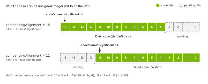
A 12-bit code stored in a 16-bit unsigned integer:
compandingAlignment = 15 places it in bits 15 to 4 (shifted left by 4);
compandingAlignment = 11 places it in bits 11 to 0 (no shift).#
To preserve all code bits, the alignment must be at least the code width minus one and at most the output integer width minus one: 15 for the 16-bit output described in Stay within 16 bits for the full pipeline. The attribute’s valid range for each integer width is on the USD attributes page.
Stay within 16 bits for the full pipeline#
The output integer type is determined by the curve. If the curve’s
last y fits in 16 bits, the companding stage writes 16-bit codes and
OmniCameraSensorPreIsp is a single-component 16-bit unsigned image; if it
does not, the stage writes 32-bit codes. The ISP accepts 16-bit input only.
Warning
When OmniCameraSensorPostIsp is requested, a curve whose last y
exceeds 65535 is refused: the pipeline is not built for that product, none
of the model’s outputs arrive, and the reason is logged as an error. Keep
the last y at or below 65535 for the full pipeline. The five-stage
pre-ISP pipeline, built when only OmniCameraSensorPreIsp is requested,
has no such limit and delivers 32-bit codes when the curve needs them.
Limitations lists this limit beside the model’s other by-design limits, and the Symptom Index has the entry for a pipeline that refused to build.
Describe the codes to the ISP#
The ISP does not read the companding attributes: author
ispSmodelSensorRawFormat for the curve’s width and
ispSmodelRawDataPaddingMode for the alignment (LEFT for alignment 15,
RIGHT for 11); the ISP group of the USD attributes page
defines both. For RAW12 at alignment 15, use LEFT padding:
int omni:sensor:core:compandingAlignment = 15
string omni:sensor:core:ispSmodelRawDataPaddingMode = "LEFT"
string omni:sensor:core:ispSmodelSensorRawFormat = "RAW12"
Supply the ISP program#
The program is yours to supply: the ovrtx package carries none. Author it in
ispSmodelCameraProgram as a base64 string on one line, beside the raw
format and padding mode of Describe the codes to the ISP; the
value is tens of kilobytes of encoded text, not something you read or type.
The ISP group of the USD attributes page
defines the attribute and its empty default, and the Primary outputs section of the Outputs page
says what the post-ISP outputs carry until a program is authored.
Request the primary output#
On the RenderProduct bound to the camera, request HdrColor and
OmniCameraSensorPostIsp, and add OmniCameraSensorPreIsp and
OmniCameraSensorPostYuvIsp while you verify. OmniCameraSensorPostIsp
is the primary output that builds the full
pipeline with the ISP in it. OmniCameraSensorPreIsp is the RAW primary
output, and OmniCameraSensorPostYuvIsp is a diagnostic tap. The output-selection rules and the
request example are on the Outputs page.
Verify it worked#
Check three things in one frame:
OmniCameraSensorPreIspis a single-component 16-bit unsigned image whose codes sit where the alignment put them. At alignment 15 with a RAW12 curve and no post-pedestal, every code is a multiple of 16 and none exceeds 65520 (4095 shifted left by 4); at alignment 11 none exceeds 4095. A 32-bit image here means the curve’s last y is above 65535 (Stay within 16 bits for the full pipeline).OmniCameraSensorPostYuvIspandOmniCameraSensorPostIsparrive in the formats the Outputs page lists and hold a picture of the scene. Look at them: the example script saves every output as a PNG preview and prints, for each, the shape, element type, minimum, maximum, mean and fraction of non-zero elements. A processed image is not empty and its values vary, with the minimum and maximum apart and the mean between them.The formats alone do not show that the ISP ran: with an empty program they are exactly the same, and only the content differs. A post-ISP image that carries no picture while
OmniCameraSensorPreIspis healthy means that no program reached the stage (Supply the ISP program).
Shape an Image Like a Camera Sensor has the checks for the earlier stages, and the Symptom Index the entries for a pipeline that was never built and for ISP taps that produce nothing.
When it goes wrong#
Each entry names the mechanism and the section that states it in full; the Symptom Index holds the full symptom text.
The companding curve’s largest output exceeds 16 bits, so the full pipeline refused to build. When
OmniCameraSensorPostIspis requested, a curve whose last y exceeds 65535 is refused: none of the model’s outputs arrive and the reason is logged as an error. Keep the last y at or below 65535 for the full pipeline; the pre-ISP pipeline alone has no such limit. Refer to Stay within 16 bits and the entry under Missing output.The ISP taps produce nothing, or nothing processed, while the earlier taps work. Either
OmniCameraSensorPostIspwas not requested, so only the pre-ISP pipeline was built and the ISP-side taps have no stage behind them, or no program is authored inispSmodelCameraProgram, the schema default, andOmniCameraSensorPostYuvIspandOmniCameraSensorPostIspare published without a processed image, in the same formats as with a program. Refer to Supply the ISP program, the primary outputs and the entry under Missing output.The padding mode does not match the alignment, or the raw format does not match the curve’s width. The ISP does not read the companding attributes: it is told the layout of the codes by
ispSmodelRawDataPaddingMode,LEFTfor alignment 15 andRIGHTfor 11, and their width byispSmodelSensorRawFormat, so author both to match what the curve and the alignment produce. Refer to Describe the codes to the ISP and the ISP group.The codes arrive without their lowest bits.
compandingAlignmentis lower than the code needs. To preserve all code bits, the alignment must be at least the code width minus one and at most the output integer width minus one. A lower position shifts the code right and discards its least significant bits. Refer to Choose the alignment and the companding group.A camera product is missing its input or its primary output.
HdrColormust sit on the same product and one of the two primary outputs has to be present as well; if either is missing, the product is skipped and an error is logged, and a tap on its own does not build a pipeline for the tap to sit on. Refer to the primary outputs, Configure the Input Image and the entry under Missing output.