

Outputs#
The Lidar generic wpm model delivers one PointCloud composite output per
requesting RenderVar. It supports no other output type. Each entry is one
return from a pulse sent by an emitter row of the firing pattern. This page
lists the channels, parameters and compact, dense and tiled layouts. See
USD Attributes for the controls that select them.
Sensor Outputs explains mapping, DLPack tensors, params,
Counts and validity flags. See Output Configuration
for RenderProduct and RenderVar setup, and the C API
or Python API for container definitions.
The model supports eight selectable channels:
CoordinatesIntensityTimeOffsetNsFlagsChannelIdMaterialIdEchoIdFiringPatternIndex
Every output also includes Counts. Compact output additionally includes
TilePointCounts and TilePointOffsets.
The model does not provide EmitterId, TickId, TickState,
ObjectId, HitNormal, Velocity, backscatter or Reflectivity.
See Lidar generic core outputs for that model’s
channels, tensor layouts and parameters.
Requesting the output#
You request the output with a RenderVar whose sourceName is
PointCloud. How channels are requested on Output Configuration
explains the channels attribute in general; this model reads the list as
follows.
An empty
channelslist selects all eight channels.An explicit list selects the channels you named, and
Flagsis added whether or not you named it.Counts, anint32tensor of shape[1], is published with every output whether or not it was asked for. In compact output, the default,TilePointCountsandTilePointOffsetsare published as well; see Compact layout.Only the eight names are produced. A name from another model’s set, or a misspelling, is not delivered, so when a channel is missing from the mapped output, check its spelling and case against the table below.
An explicit list must name at least one of the eight channels;
Counts,TilePointCountsandTilePointOffsetscome with every output but do not count as names here. A list that names none of the eight is rejected and the reason is logged as an error; correct the list before the sensor can publish.
For an existing WPM lidar at /Lidar, this example requests coordinates,
intensity and firing-time offsets. Flags and Counts are included
automatically, along with the tile tensors when using compact output.
#usda 1.0
def RenderProduct "LidarProduct"
{
    rel camera = </Lidar>
    rel orderedVars = [</PointCloud>]
}

def RenderVar "PointCloud"
{
    uniform string sourceName = "PointCloud"
    token[] channels = ["Coordinates", "Intensity", "TimeOffsetNs"]
}
from pxr import Sdf, UsdRender

product = UsdRender.Product.Define(stage, "/LidarProduct")
# Target the existing WPM lidar prim.
product.GetCameraRel().SetTargets(["/Lidar"])
point_cloud = UsdRender.Var.Define(stage, "/PointCloud")
point_cloud.GetSourceNameAttr().Set("PointCloud")
# Select channels; Flags and Counts are included automatically.
point_cloud.GetPrim().CreateAttribute(
    "channels", Sdf.ValueTypeNames.TokenArray, custom=False
).Set(["Coordinates", "Intensity", "TimeOffsetNs"])
product.GetOrderedVarsRel().SetTargets([point_cloud.GetPath()])
The rotary example
on Configure a Firing Pattern requests the default set with
token[] channels = []; its solid-state example names
six channels explicitly.
Multiple PointCloud outputs#
One RenderProduct can request several PointCloud RenderVars with separate
channels lists. The model runs one scan and computes their combined channel
set, then publishes each RenderVar’s selected channels with Flags,
Counts and, for compact output, tile tensors. All outputs contain the same
points: counts and slot indices agree. Outputs are identified by
RenderVar prim path.
Channels#
In the shapes below, Nmax is the point capacity, published as the
maxPoints param: the number of slots the output has room for, not the
number of returns it holds. Which slots carry a return depends on the layout:
in compact output read the first Counts[0] slots, in dense output select by
Flags. Both layouts are described further down.
Channel |
Type |
Shape |
Unit |
Meaning |
|---|---|---|---|---|
|
|
|
m, deg |
Cartesian |
|
|
|
unitless |
Presented intensity in the configured processing mode. |
|
|
|
ns |
Firing time of the return relative to the output’s |
|
|
|
unitless |
Validity: the valid bit is set on a slot that holds a return. |
|
|
|
unitless |
The detector channel id of the emitter row, exactly as authored on the firing pattern. |
|
|
|
unitless |
Encoded non-visual material identifier of the hit surface. |
|
|
|
unitless |
Index of the return among the returns of its emitter row, from |
|
|
|
unitless |
Zero-based position of the pattern that fired the return, in the lexicographic order of the pattern instance names. |
Coordinates has shape [Nmax, 3], with each point’s three components
adjacent in memory. Use the descriptor’s strides when reading it.
SPHERICAL encoding (default) stores [azimuthDeg, elevationDeg, rangeM];
CARTESIAN stores [xM, yM, zM]. Both use the configured
reference frame.
See the ISO 8855 sensor convention for axes and angular units.
The Lidar generic core model uses component-first packing ([3, Nmax]).
A reader must account for this difference when switching models; see
tensor packing.
Intensity uses the configured processing, mapping and scale. These
settings are not reported in the output, so the consumer must retain them.
omni:sensor:LidarWpm:intensityProcessing selects rangeNormalized
(default) or raw; mapping and scale control the reported value.
There is no separate reflectivity or backscatter channel.
See Tune Intensity for the conventions. These settings
do not change return detection.
TimeOffsetNs records each return’s firing time relative to timestampNs,
the scan start. Request it when the consumer performs motion compensation.
The signed 32-bit nanosecond count has a maximum of 2147483647 ns, about
2.147 s. Keep the scan rate at or above roughly 0.47 Hz to avoid exceeding
that range. Other models use different reference times for this channel;
see shared channel names.
Flags marks valid returns with the VALID bit (0x40). This model
sets no other bits. Test the bit as described in
Checking validity; see the
compact and
dense layouts for which
slots to read.
ChannelId reports the detector channel id authored on the firing pattern.
Ids are labels, not indices; see channel-id constraints and cost on USD Attributes.
Dense output writes 0 to invalid slots, but 0 is also a valid detector
id. Select valid slots with Flags before reading ChannelId.
MaterialId identifies the hit surface’s non-visual material. It uses the
same encoding as the Lidar generic core model; see its
bit layout and decoding example. Only the two lidar models
report material ids. See Non-Visual Sensor Materials
for the meaning of 0 and how to verify material labels.
EchoId numbers the returns retained by an emitter row, from 0 to
maxReturns - 1. In waveform mode, returns are ordered by decreasing
detected signal strength, with nearer returns first on ties, including
saturation. This signal is the value reported by raw intensity processing
(Tune Intensity); rangeNormalized intensity need not decrease with
EchoId. In the two direct modes, returns follow the order in which the
pulse’s path encountered their surfaces. EchoId is a uint8, which
limits omni:sensor:LidarWpm:maxReturns; see the
scan-schedule table
on USD Attributes.
FiringPatternIndex is the zero-based position of the firing-pattern
instance in lexicographic order, which also determines
firing order.
Adding, removing or renaming an earlier instance shifts later indices. Do
not use it as a persistent pattern identifier. Dense output fills it for every
slot, including invalid slots, using the pattern of that slot’s emitter row.
Coordinates and motion compensation#
Four attributes under omni:sensor:LidarWpm: control the returned coordinates:
elementsCoordsType: Cartesian or spherical coordinates.outputFrameOfReference: sensor, world or custom reference frame.customFrameOfReferenceTrafo: the transform used for the custom frame.outputMotionCompensationState: whether to compensate for sensor motion during the scan.
See coordinate attributes for values, units and defaults.
Each point is reconstructed in Cartesian sensor coordinates from the receiver’s direction and the detected range. The reference-frame and compensation settings then determine its transform, as shown below. The transformed point is returned in the selected Cartesian or spherical representation.
The table uses two sensor poses:
Scan-start pose: the sensor pose at the output’s
timestampNs.Fire-time pose: the sensor pose at the return’s firing time, interpolated over the scan’s motion interval.
Set outputMotionCompensationState to true to enable compensation or
false to disable it.
Reference frame |
Compensation disabled |
Compensation enabled |
|---|---|---|
|
Return the point in its original sensor coordinates. |
Transform the point to world coordinates using its fire-time pose, then into the scan-start sensor frame. This removes distortion caused by sensor motion during the scan (deskewing). |
|
Transform all points using the scan-start pose. |
Transform each point using its fire-time pose. |
|
Apply the custom transform to the point’s original sensor coordinates. |
Compensate as for |
The defaults are SPHERICAL coordinates in the SENSOR frame with
compensation disabled. Azimuth, elevation and range then come directly from
the receiver direction and detected range, without a sensor-motion correction.
Other settings transform the point before encoding it. Spherical coordinates
in WORLD or CUSTOM are measured from the selected frame’s origin.
Compensation corrects sensor motion, not target motion. It has no effect when
the sensor is stationary. The output parameters coordsType,
frameOfReference and motionCompensationState report the settings used.
An accepted edit to these four attributes applies to all detected and deferred
returns in the next published output. Each point cloud uses one coordinate
encoding. The edit preserves validity, Counts, ChannelId, EchoId,
FiringPatternIndex and return order. See
presentation-only updates for these
updates and Retune the Sensor While It Runs for rejection behavior.
Motion#
Motion within a frame requires the renderer’s motion BVH, selected at renderer creation. See motion BVH configuration and Motion Artifacts for examples with and without it.
Without motion BVH, the model still publishes outputs. Each frame traces from
the sensor’s end pose against a static scene, so its points contain no
intra-frame motion effects, even though TimeOffsetNs retains the firing
times. Tile start poses come from the end of the scan’s first frame; end poses
come from the end of its latest contributing frame. These can differ across
a multi-frame scan, and motion compensation interpolates between them. Enable
motion BVH when evaluating motion effects or deskewing.
Params#
Output parameters apply to the entire point cloud and are stored in CPU memory.
See parameter access. This model
publishes the thirteen shared params, the lidar-specific
compactionType and motionCompensationState, and additional tile and
layout params listed below. Read params by name and ignore unrecognized names.
Param |
Type |
Shape |
Meaning |
|---|---|---|---|
|
|
|
The point capacity |
|
|
|
Always |
|
|
|
The start time of the scan the returns belong to, in nanoseconds;
|
|
|
|
|
|
|
|
|
|
|
|
Start of the first frame window that contributed to the published scan.
For a scan delivered whole and stepped at its own period or a divisor of
it, this is |
|
|
|
End of the latest frame window that contributed. For a completed scan
with |
|
|
|
Tile zero’s position at the two bounds of the interval, in meters, in the world frame. |
|
|
|
Tile zero’s orientation at the two bounds, as a unit quaternion ordered
|
|
|
|
One start and one end position per tile, in meters, in |
|
|
|
One start and one end orientation per tile, |
|
|
|
|
|
|
|
The identity for this model. |
|
|
|
|
|
|
|
|
|
|
|
Always |
|
|
|
The number of sensors in the product’s |
|
|
|
The number of emitter rows the schedule keeps for one sensor, every tick of a rotary scan and every pattern of a solid-state one, after subsampling. |
|
|
|
The return capacity per emitter row, the authored
|
|
|
|
The slot capacity of the published layout, equal to |
|
|
|
Dense output: the slot distance between tiles, |
|
|
|
Dense output: the slot distance between emitter rows, |
Which steps deliver an output follows from
omni:sensor:LidarWpm:partialOutputs and
omni:sensor:LidarWpm:instantLidar, explained under output shaping on USD Attributes.
Sensor Scheduling covers stepping sensors that deliver at
different rates.
Compact layout#
Compact output is the default (omni:sensor:LidarWpm:includeInvalidPoints = false).
Valid returns occupy slots [0, Counts[0]), ordered by tile, then emitter row,
then return within the row. Compaction preserves that order.
Read only the first Counts[0] entries. The remaining slots have zero
Flags and unspecified channel values; see read bounds. Point tensors retain their
capacity shapes, [Nmax] or [Nmax, 3], regardless of the return count.
compactionType is 2.
Two additional tensors locate each tile’s returns in rel camera order:
TilePointCounts: auint64tensor of shape[tileCount]containing the number of returns from each tile. Its entries sum toCounts[0].TilePointOffsets: auint64tensor of shape[tileCount + 1]. Tile t occupies slots[TilePointOffsets[t], TilePointOffsets[t + 1]). The first offset is0and the last isCounts[0].
For one sensor, these tensors contain [Counts[0]] and [0, Counts[0]],
respectively.
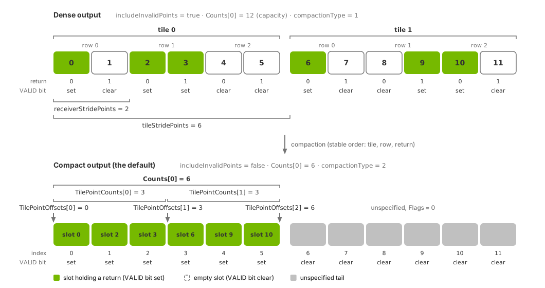
Dense (top) and compact (bottom) layouts for two tiles, each with three
emitter rows and two return slots per row. Dense output retains all 12
slots, ordered by tile, emitter row and return; Flags identifies valid
returns. tileStridePoints = 6 and receiverStridePoints = 2 locate
tiles and rows. Compact output packs valid returns into the first
Counts[0] slots. For tile counts c0 and c1,
TilePointCounts = [c0, c1] and TilePointOffsets = [0, c0, Counts[0]].
Gray slots are unused and their values are unspecified.#
Dense layout#
Set includeInvalidPoints = true to retain a slot for every possible
return. Each point channel has capacity
tileCount * receiversPerTile * maxReturns, with slots indexed as follows:
slot = tile * tileStridePoints + emitterRow * receiverStridePoints + return
The index uses:
tileStridePoints:receiversPerTile * maxReturns, reported as an output parameter.receiverStridePoints:maxReturns, also reported as an output parameter.emitterRow: the row index among those retained by the tile’s scan schedule.
Filter slots using the Flags valid bit. Counts[0] reports capacity,
not the number of valid returns. compactionType is 1.
Invalid slots contain zero in Coordinates, Intensity, TimeOffsetNs,
ChannelId, MaterialId and EchoId. FiringPatternIndex is populated
for every slot. Dense output has no TilePointCounts or TilePointOffsets
tensors; use the strides to locate each tile.
Tiled aggregates#
When several WPM lidars share a RenderProduct’s camera relationship, they
use one scan schedule and the first sensor’s attributes. Each PointCloud
RenderVar returns one combined point cloud. See Tile Lidars for
setup and verification.
Locate each sensor’s returns using compact-layout tile tensors or dense-layout strides. For separate point clouds, use one RenderProduct per sensor. The Lidar generic core model requires separate RenderProducts.
Startup outputs#
During initialization, accepted PointCloud requests return empty outputs:
Coordinateshas shape[0, 3]; other point channels have shape[0].Counts[0]andvalidPointCountare zero.Compact output includes zeroed
TilePointCountsandTilePointOffsets.maxPointsreports the configured capacity.timestampNsis the frame end time.
Other layout parameters, coordinate settings and channel types match the configured sensor. Unlike normal outputs, startup point tensors have zero length rather than capacity-sized shapes. Readers bounded by the count or tensor length need no special case.
Initialization performs no tracing or return accumulation, but scan timing continues to follow the simulation clock. The first populated output therefore belongs to the scan window active when initialization finishes. Empty startup outputs are expected.
Reading the output#
Follow the mapping,
synchronization and
lifetime rules for CPU or CUDA
access. Read each tensor’s data type, shape and strides from its DLPack descriptor and bound point reads by Counts[0].
Compact output stores valid returns in
[0, Counts[0]); tile tensors locate each tile’s range.Dense output reports capacity in
Counts[0]. Filter by theFlagsvalid bit and locate tiles and emitter rows using strides.Startup output has zero-length point tensors and a zero count.
Read coordsType, frameOfReference and motionCompensationState to
interpret the coordinates; see coordinate conversion. The
rotary example
produces this output. Read its coordinates with
point-first indexing.