

USD Attributes#
The Camera single-view stereo depth model has fourteen
omni:sensor:depthSensor:* attributes: optics, noise and quantization,
confidence, range limits, and visualization. Unauthored values use the schema
defaults listed in Sensor API Schemas.
Apply OmniSensorGenericDepthSensorSingleViewAPI to the Camera prim.
Without it, or with a second sensor schema on the same camera, the model
produces no output.
Where the schema applies#
Everything is authored on the Camera prim the product renders through.
OmniSensorGenericDepthSensorSingleViewAPI is a single-apply API schema that the
sensor schema restricts to Camera prims, and applying it brings the fourteen
attributes with it, all in one namespace. There is no sensor prim. The schema
also brings the shared omni:sensor:* attributes: the
identity strings modelName,
modelVendor and marketName. What the product delivers comes from the
attribute values on its
camera. How to apply the schema and request the outputs is on
Set Up a Depth Product.
One attribute, enabled, has no effect in ovrtx: requesting the model’s
outputs on the product enables the post-processing pipeline, as The required set on the Outputs page
describes; Limitations lists it. The
other fourteen are the subject of this page.
Optics and disparity#
This is the group that reshapes the output. A stereo camera turns disparity into distance (the overview defines the term); this model runs that relation backwards, taking each pixel’s rendered distance and writing it into the pixel where a second imager, displaced by the baseline, would have seen it (the reprojection). Three attributes, together with the product’s width, decide how much disparity a given distance produces, and a fourth caps it. Together they set the depth resolution at every distance, the width of the occlusion holes (the regions only one imager can see) and the closest distance the sensor can see.
disparity_px = width_px * baselineMM * focalLengthPixel
               / sensorSizePixel / (distance_m * 1000)
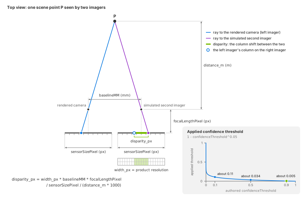
Disparity geometry (schematic, not to scale). Two imagers separated by
baselineMM see a point at
distance distance_m in different columns. The disparity is the column
shift expressed in pixels at the product’s resolution. The reference imager
is sensorSizePixel pixels wide with focal length focalLengthPixel.
The inset shows the applied confidence threshold as a function of the authored
confidenceThreshold.#
focalLengthPixel should match the real camera’s horizontal focal length in
pixels, and sensorSizePixel should match the image width at which that focal
length is specified. Use the calibrated horizontal focal length (fx) and
image width from the same camera mode. For a physical imager, these values can
also be calculated from its focal length, active width and horizontal pixel
pitch, all expressed in millimeters:
focalLengthPixel = focal_length_mm / pixel_pitch_mm
sensorSizePixel = active_sensor_width_mm / pixel_pitch_mm
Use the active image area and pixel spacing for the selected mode, including
any crop, binning or resizing. A calibration for that mode already accounts for
these changes. sensorSizePixel is a horizontal pixel count.
Configure the rendered camera from the same intrinsics. For a pinhole camera with a matching field of view, the relationship is:
focalLengthPixel / sensorSizePixel
    = Camera.focalLength / Camera.horizontalAperture
The Camera prim’s focal length and aperture use the same length unit, so their ratio is independent of that unit. The depth attributes are authored separately and are not automatically derived from the Camera prim. Set the rendered projection as USD Camera Attributes describes.
width_px is the product’s horizontal resolution, the first component of
resolution on the RenderProduct
(Output Configuration). The model
scales the reference focal length to this width:
effective_focal_length_px = focalLengthPixel * width_px / sensorSizePixel
When rendering the same field of view at another resolution, keep the reference
focalLengthPixel and sensorSizePixel pair together. If you instead use a
calibration at the new resolution, update both values from that calibration.
Changing sensorSizePixel alone changes the modeled intrinsics. Doubling the
product width doubles disparity in output pixels; scale maxDisparityPixel
accordingly to preserve the near limit, as shown in
Build a Profile from a Spec Sheet.
Attribute |
What it does |
|---|---|
|
Distance between the two simulated imagers, in millimeters. Match the real device’s baseline. The sign determines the horizontal reprojection direction, so a negative value is allowed. A larger baseline increases disparity, improves far-range depth resolution and widens occlusion holes. |
|
Horizontal focal length in pixels at the reference image width
|
|
Reference image width in pixels, from the same camera mode or calibration
as |
|
Largest disparity the sensor can resolve, in rendered-image pixels. Match the device’s disparity limit, converted to the product’s resolution. A sample whose disparity exceeds it is discarded during reprojection, which sets the near limit of the sensor. The worked example is on Build a Profile from a Spec Sheet. |
Noise and quantization#
Three attributes shape the noise, and they act on the disparity, not on the
distance. For each pixel and each frame, a standard-normal sample is scaled by
noiseSigma, added to the disparity, and the result is rounded to a multiple
of noiseMean. The sample is then written at the pixel that the perturbed
disparity specifies. The model perturbs the measurement’s pixel position while
preserving its distance value, which is how a disparity-quantized sensor
behaves: a whole-pixel disparity step is a larger distance step far away than
near.
The random draw is repeated every frame, so the noise is temporal as well as
spatial: a static scene does not produce a static depth image.
noiseDownscaleFactorPixel coarsens the noise field so that neighboring pixels
share one sample.
These are processing parameters measured on the rendered image’s pixel grid. Set them from the device’s disparity precision and measured noise behavior. Physical pixel pitch is used to convert the optical dimensions above; it is not a value for these noise attributes. Convert measurements made at a different image resolution to the product’s pixel grid before tuning.
Setting noiseMean to 0 switches noise and quantization off together;
Tune Noise, Quantization and Confidence walks
through the noise-free run and through shaping the noise.
Attribute |
What it does |
|---|---|
|
Quantization step of the disparity, in rendered-image pixels. |
|
Standard deviation of the Gaussian jitter added to the disparity before quantization, in rendered-image pixels. |
|
Coarseness of the noise field, in rendered-image pixels. At |
Confidence#
Three attributes control which pixels have valid depth measurements. The
confidence test is binary and evaluated at each sample’s source pixel in the
rendered view. A sample is accepted when its combined confidence exceeds
1 - confidenceThreshold^0.05. Combined confidence is the sum of two terms:
Texture: an edge (gradient) measure of the luminance image, saturated to the 0–1 range. This is why raising the scene’s texture detail, or its lighting contrast, increases depth coverage, and why a plain wall produces nothing. The measure needs a neighborhood, so the outermost ring of pixels contributes no texture confidence.
Simulated IR projection, when
effectiveDistanceis greater than zero:(effectiveDistance / distance)², saturated to 1. Within the effective distance this term equals 1 and exceeds any applied threshold below 1, so a surface is accepted regardless of texture. Beyond that distance, the term decreases proportionally to the inverse square of distance. At the default of0.0the term is zero and only texture counts.
The applied threshold is 1 - confidenceThreshold^0.05. This nonlinear
mapping decreases from 1 to 0 as the authored value increases from 0 to 1.
An authored value of 0.9 gives an applied threshold near 0.005:
Authored |
Applied confidence threshold |
|---|---|
|
|
|
about |
|
about |
|
about |
|
|
At an authored value of 0.0, the applied threshold is 1. Texture confidence
alone cannot exceed 1, so acceptance requires contributions from both texture
and the IR term. At 1.0, the applied threshold is 0, so any pixel with
positive combined confidence passes.
Warning
Increasing confidenceThreshold lowers the applied threshold and accepts
more pixels. Decreasing it requires greater combined confidence.
Attribute |
What it does |
|---|---|
|
How permissive the confidence test is, remapped as above. A higher authored value keeps more pixels. |
|
Range of the simulated IR projector, in meters, the unit of the distance
output (Outputs says why). |
|
Cleanup along each row after reprojection: a single invalid pixel between two valid neighbors is filled with the farther of them, and a single valid pixel between two invalid neighbors is removed. The cleanup needs both row neighbors, so it skips the leftmost and rightmost columns. On by default. |
Range limits#
Two attributes bound what is reported. minDistance and maxDistance are in
meters, like the distance output (Outputs explains the unit).
These filters are applied at several stages. The final write rejects distances
less than or equal to minDistance or greater than or equal to
maxDistance. Author minDistance below maxDistance: otherwise, the
model clamps it to just below maxDistance, leaving a very narrow interval
of accepted distances.
These attributes apply explicit distance filters. maxDisparityPixel
separately determines the minimum distance implied by the stereo geometry.
The distance filters also define the interval used by the grayscale and rainbow
visualizations, modes 2 and 3. With the default maxDistance of
10000000.0, normalization over ten million meters maps typical scene
distances to nearly the same value. Both images therefore appear effectively
uniform. Author a realistic maxDistance before using mode 2 or 3.
Attribute |
What it does |
|---|---|
|
Near cutoff, in meters, inclusive: a distance at or below it is no measurement. Also the near end of the visualization gradient. |
|
Far cutoff, in meters, inclusive: a distance at or above it is no measurement. Also the far end of the visualization gradient. |
Visualization and diagnostics#
Two attributes serve inspection rather than measurement. rgbDepthOutputMode
selects which diagnostic image the DepthSensorOutputVisualization output
contains; the mode table, the fallback for values outside it, and what each image
can and cannot tell you are on Outputs. showDistance marks the
center pixel of that visualization red and prints the center pixel’s distance
and disparity to standard output, a quick check of a parameterization against a
target at a known distance. The readout is the rendered distance and the
disparity your optics give for it, printed whether or not that sample passes
the range and disparity filters, so it is not the filtered sensor measurement.