

Constrain the Field of View#
The Lidar generic core model filters returns by range and, for rotary scans, azimuth. These limits define the accepted field of view; they do not aim the emitters. A separate region of interest applies different distance limits within part of the scan.
Before you start, use a sensor configured using Configure a Firing Pattern. The firing pattern determines ray directions; the limits below filter its returns.
Field-of-view controls#
The example sets the schema defaults for range and rotary azimuth limits.
They accept a full turn and ranges up to 200 m. With the default ray type,
minDistBetweenEchosM also limits the minimum range; see
range limits.
#usda 1.0

def OmniLidar "generic_lidar" (
    prepend apiSchemas = ["OmniSensorGenericLidarCoreAPI"]
)
{
    float omni:sensor:Core:nearRangeM = 0.3
    float omni:sensor:Core:farRangeM = 200
    float omni:sensor:Core:validStartAzimuthDeg = 0
    float omni:sensor:Core:validEndAzimuthDeg = 360
}
from pxr import Gf, Sdf

generic_lidar = stage.DefinePrim("/generic_lidar", "OmniLidar")
generic_lidar.AddAppliedSchema("OmniSensorGenericLidarCoreAPI")
generic_lidar.CreateAttribute(
    "omni:sensor:Core:nearRangeM", Sdf.ValueTypeNames.Float, custom=False
).Set(0.3)
generic_lidar.CreateAttribute(
    "omni:sensor:Core:farRangeM", Sdf.ValueTypeNames.Float, custom=False
).Set(200.0)
generic_lidar.CreateAttribute(
    "omni:sensor:Core:validStartAzimuthDeg", Sdf.ValueTypeNames.Float, custom=False
).Set(0.0)
generic_lidar.CreateAttribute(
    "omni:sensor:Core:validEndAzimuthDeg", Sdf.ValueTypeNames.Float, custom=False
).Set(360.0)
The meaning, units and relations of every attribute named on this page are on USD Attributes; the type and default of each is in the generated Sensor API Schemas.
Four validity limits#
nearRangeM and farRangeM bound the return distance.
validStartAzimuthDeg and validEndAzimuthDeg bound rotary firing angles.
Returns outside these limits are invalid and dropped by default. With
includeInvalidPoints = true, their slots remain in the output with the
validity bit clear; see Outputs.
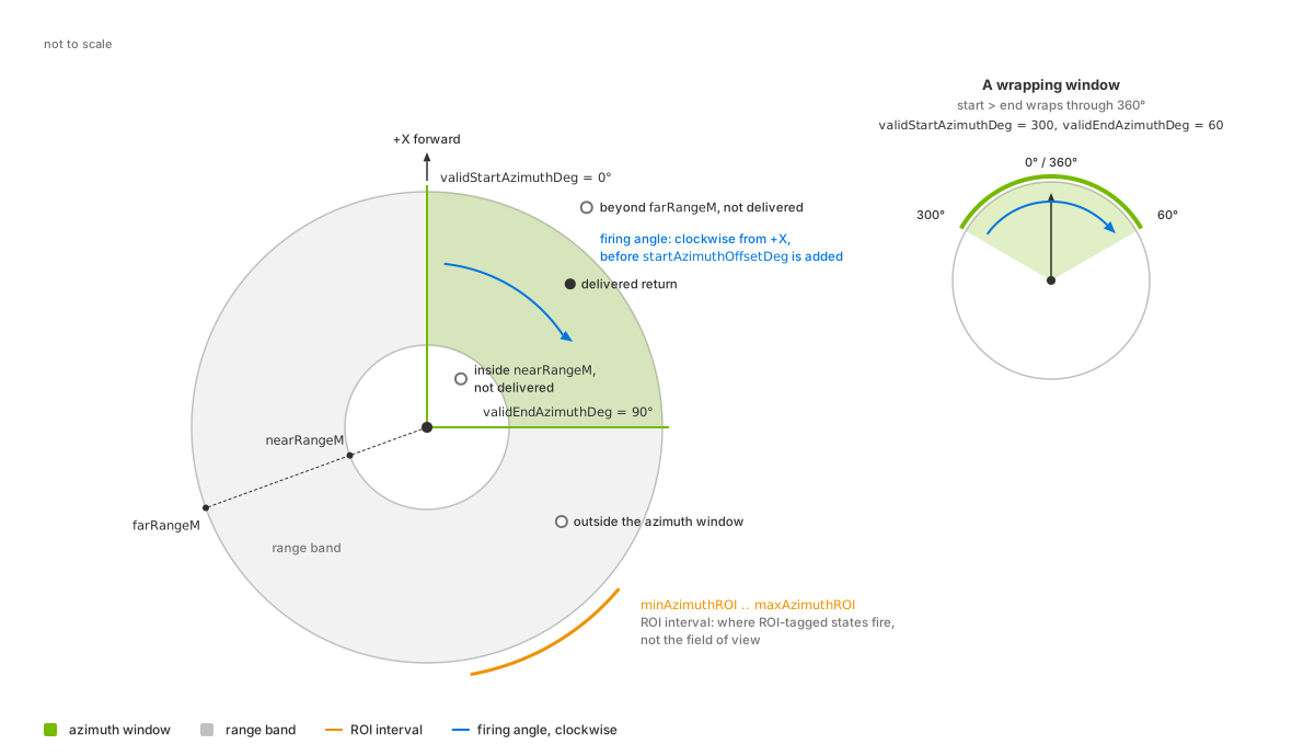
The three windows seen from above: the range band between nearRangeM
and farRangeM, the azimuth window from validStartAzimuthDeg to
validEndAzimuthDeg with a second example that wraps through 360
degrees, and the region of interest as a separate arc. The window is drawn
on the firing angle; the angle-conventions figure on the
attributes page relates it to the delivered azimuth.#
Range limits#
Returns must lie between nearRangeM and farRangeM. For the default
IDEALIZED rays, minDistBetweenEchosM imposes an additional near limit;
its default of 0.4 m exceeds the default nearRangeM.
For per-emitter range windows, set rangeCount, provide rangesMinM and
rangesMaxM arrays of that length, and select a window for each emitter
with emitterState:s#:rangeId. These windows replace the range band for
the emitters using them. See Configure a Firing Pattern for emitter arrays and
range attributes for
defaults and validation rules.
Rotary azimuth limits#
validStartAzimuthDeg and validEndAzimuthDeg restrict rotary scans.
Solid-state angular coverage comes from the emitter arrays; see
Configure a Firing Pattern. Both boundaries are inclusive.
The limits apply to the firing angle, which differs from the delivered azimuth. See the angle-conventions figure and the verification procedure below. Defaults, wrapping and sweep direction are described under field-of-view attributes.
Filtering is independent of delivery cadence. With partialOutputs = false
(default), each completed scan contains all accepted returns, including those
in a window that wraps through 360 degrees. With true, each step delivers
accepted returns from its portion of the scan; see Configure Lidar Output.
Region of interest#
minAzimuthROI and maxAzimuthROI do not narrow the point cloud: they
confine the emitter states tagged with emitterState:s#:isROIState to an
interval of the rotation and leave the untagged states unconfined. To narrow
what the sensor delivers, use the azimuth pair; the defaults, the wrap rule, which angle the
interval is tested against and the tagging arrays are under field of view, range and orientation.
Verification#
Request Coordinates on the PointCloud RenderVar and read entries
[0, Counts[0]); see Sensor Outputs. Use the defaults
outputFrameOfReference = SENSOR and
outputMotionCompensationState = NONCOMPENSATED for these checks; see
Configure Lidar Output.
Read coordsType from each frame to determine its representation. For
1, coordinates are azimuth and elevation in degrees, followed by distance
in meters. For 0, calculate range from the vector norm and heading with
atan2(y, x). Output parameters describe the settings actually used; an
authored runtime edit may not yet apply to an in-flight frame. See
Outputs for parameter definitions. Check the resulting values:
Every delivered range lies within
[nearRangeM, farRangeM]or, when the profile authorsrangesMinMandrangesMaxM, within the window its emitter’semitterState:s#:rangeIdselects. RequestEmitterIdandTickStateto identify the emitter and the state an entry came from, and read itsrangeIdfrom that state’s array.On a rotary sensor, every delivered azimuth lies inside the azimuth window once it is taken back to the angle the window is measured in. The delivered azimuth is measured the other way round and includes
startAzimuthOffsetDeg, as Outputs states, so reduce-azimuth - startAzimuthOffsetDegmodulo 360 into[0, 360)for each entry, and check that the result falls in the interval fromvalidStartAzimuthDegtovalidEndAzimuthDeg, which wraps through 360 degrees when the start is greater than the end.
Allow a small boundary tolerance. Filtering follows range and azimuth error, so those errors do not move accepted returns outside the windows. However, filtering measures from the emitter while output coordinates reference the sensor prim. Emitter offsets and coordinate-rounding errors can therefore put delivered coordinates slightly beyond a limit.
Narrow one limit and repeat the check with partial outputs both enabled and disabled. The corresponding data boundary should move. Counts can vary with noise and intensity filtering, but accepted returns must still satisfy the windows.
If compactionType = 1, invalid slots are included. Select entries with
the Flags valid bit before testing either window; see Outputs.
Potential issues#
See the Symptom Index for additional causes and checks.
A nearby object never appears while distant ones do: it is inside the near range, or nearer than
minDistBetweenEchosM.The point cloud covers the whole turn although an ROI was authored: the ROI attributes do not narrow the field of view. Use the azimuth pair for that, and see what the ROI window does.
An authored ROI does not take effect: an ROI needs both
minAzimuthROIandmaxAzimuthROIauthored below 400 and at least one emitter state tagged withemitterState:s#:isROIState. Leave any of the three out and no ROI is configured; see what the ROI window does.An ROI that appears to cover the opposite side of the sensor: a
minAzimuthROIgreater thanmaxAzimuthROIis a wrapping interval rather than an error.The azimuth limits do nothing at all: the sensor is solid state, where they do not apply.