

Outputs#
The Lidar generic core model delivers a PointCloud composite output for
each requesting RenderVar. Each entry is one return from an emitter firing.
This page defines the channels, parameters, layouts and delivery timing.
See USD Attributes for controls, and Sensor Outputs
for mapping, DLPack access, synchronization and lifetime.
The Lidar generic wpm model publishes its own channel set and layout, listed on Outputs.
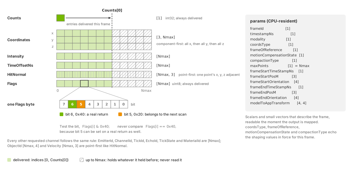
One mapped PointCloud output of this model: the per-point channels
with their shapes (Coordinates component-first, HitNormal
point-first), the delivered range [0, Counts[0]) against the capacity
Nmax, the two Flags bits, and the params beside the tensors.#
Requesting the output#
Set the RenderVar’s sourceName to PointCloud and list the desired
channels. Counts and Flags are always included. Unrecognized
channel names are ignored with a warning. See
Output Configuration and
channel selection.
Channels such as Coordinates and Intensity are available only inside
PointCloud. A RenderVar that uses a channel name as its sourceName
receives no output.
Each RenderProduct supports one sensor, selected by rel camera.
Counts has shape [1]. Give each additional sensor
its own RenderProduct;
see sensor configuration.
The lidar example scene authors this request:
#usda 1.0
    def "Render"
    {
        def "Products"
        {
            def RenderProduct "LidarProduct"
            {
                rel camera = </World/Lidar>
                rel orderedVars = [<../../Vars/PointCloud>]
            }
        }

        def "Vars"
        {
            def RenderVar "PointCloud"
            {
                uniform string sourceName = "PointCloud"
                token[] channels = [
                    "Coordinates",
                    "Intensity",
                    "Counts",
                    "TimeOffsetNs"
                ]
            }
        }
    }
from pxr import Gf, Sdf

world = stage.DefinePrim("/World", "Xform")

render = stage.DefinePrim("/World/Render", "")

products = stage.DefinePrim("/World/Render/Products", "")

lidar_product = stage.DefinePrim("/World/Render/Products/LidarProduct", "RenderProduct")
lidar_product.CreateRelationship("camera", custom=False).SetTargets(["/World/Lidar"])
lidar_product.CreateRelationship("orderedVars", custom=False).SetTargets(
    ["/World/Render/Vars/PointCloud"]
)

vars = stage.DefinePrim("/World/Render/Vars", "")

point_cloud = stage.DefinePrim("/World/Render/Vars/PointCloud", "RenderVar")
point_cloud.CreateAttribute(
    "sourceName", Sdf.ValueTypeNames.String, custom=False, variability=Sdf.VariabilityUniform
).Set("PointCloud")
point_cloud.CreateAttribute("channels", Sdf.ValueTypeNames.TokenArray, custom=False).Set(
    ["Coordinates", "Intensity", "Counts", "TimeOffsetNs"]
)
Channels#
A firing can produce zero, one or multiple returns. EchoId identifies
returns from the same firing. maxReturns limits the number retained per
channel, and minDistBetweenEchosM sets their minimum resolved separation;
see USD Attributes. The available channels are:
Channel |
Type |
Shape |
Unit |
Meaning |
|---|---|---|---|---|
|
|
|
points |
Number of point entries delivered this frame; bounds every other per-point channel. Delivered whether or not requested. |
|
|
|
unitless |
Per-point status bits. The |
|
|
|
m, deg |
Position of the return, component-first.
|
|
|
|
unitless |
Return strength after |
|
|
|
ns |
Firing time of this return relative to the frame’s |
|
|
|
unitless |
Zero-based index of the emitter within its emitter state. |
|
|
|
unitless |
The detector id of the emitter that produced the point, exactly as
authored in the emitter state’s |
|
|
|
unitless |
Zero-based, scan-local index of the tick the point came from. |
|
|
|
unitless |
Index of this return within its firing, counting from |
|
|
|
unitless |
Zero-based index of the emitter state that fired the point. |
|
|
|
unitless |
Encoded non-visual material identifier of the hit geometry; |
|
|
|
unitless |
128-bit stable identifier of the hit object, point-first, four values per point. |
|
|
|
unitless |
Unit surface normal at the hit point, point-first. |
|
|
|
m/s |
Velocity of the hit point relative to the sensor, point-first. |
Counts and validity#
Read entries within [0, Counts[0]). With invalid points included, select
returns using the Flags bit 0x40. This model can also set the
new-scan bit (0x20),
so test the valid bit rather than comparing the entire value. See
reading the output.
Coordinates and frames#
elementsCoordsType selects Cartesian or spherical components.
outputFrameOfReference selects SENSOR, WORLD or CUSTOM;
customFrameOfReferenceTrafo defines the custom frame.
outputMotionCompensationState controls compensation for sensor motion.
See USD Attributes for these controls. Read coordsType and
frameOfReference to identify the representation used for a delivered
frame; an authored edit may not yet apply to that frame.
Cartesian components are x, y and z in meters; spherical components are
azimuth, elevation and distance, in that order. The SENSOR frame, with the
units and ranges of the spherical components, is what
The sensor frame defines for every non-visual
output; the modelToAppTransform param carries the rotation from that frame
to the application’s axes.
The delivered azimuth and the firing angle are two conventions. A
delivered azimuth runs counter-clockwise from +X in (-180, 180] and
includes omni:sensor:Core:startAzimuthOffsetDeg. The firing angle that the
azimuth window of a rotary sensor is measured in runs clockwise from +X,
before that offset is added. Compare a delivered azimuth with
validStartAzimuthDeg and validEndAzimuthDeg only after converting it;
the conversion recipe and the window check are on
Constrain the Field of View under the azimuth window, and the angle diagram is on
USD Attributes.
Emitter offsets horOffsetM and vertOffsetM affect both traced rays
and delivered positions. The horizontal offset rotates with a rotary head.
Detection and range limits measure distance from the emitter, while output
coordinates include its displacement from the sensor prim’s origin. This
applies in every reference frame and representation, including spherical
SENSOR coordinates. Do not add the offset again. See
Configure a Firing Pattern for configuration.
Both front and back faces of a surface can produce returns.
Intensity#
Intensity reports return strength after processing, clipping, mapping
and scaling. intensityProcessing selects RAW, NORMALIZATION
(default) or CORRECTION. intensityMappingType and
intensityScalePercent control the output transfer and scale; see
intensity attributes.
Compare values only between runs with compatible intensity settings and materials.
Detection uses the signal before clipping. A threshold above 1 therefore
retains sufficiently strong returns, but all report the maximum intensity:
intensityScalePercent / 100 under LINEAR mapping. See
detection thresholds in
Tune Intensity and Point Drops.
Timing: TimeOffsetNs#
TimeOffsetNs measures firing time relative to timestampNs, which
equals frameStartTimeStampNs for this model. Emitters can fire at
different times within one tick, according to fireTimeNs. With
instantLidar, all offsets are zero; see
instant lidar.
The signed 32-bit nanosecond representation limits scan duration and imposes
the minimum positive scan rate.
Request this channel for application-side deskewing of NONCOMPENSATED
output; see Motion Artifacts. Other models can use a different
reference instant for the same channel name; see
shared names.
Firing identifiers#
The following channels identify each point’s position in the firing pattern.
EmitterId#
EmitterId is the zero-based index of the emitter within its emitter state,
the position of its entries in the state’s per-emitter arrays. On a
solid-state sensor it is the complete record of the pattern: with
partialOutputs off and includeInvalidPoints on, every scan the sensor
traced in full carries each EmitterId from 0 through
numberOfEmitters - 1, each exactly once when numberOfChannels equals
numberOfEmitters and maxReturns is 1. That invariant is the
verification Configure a Firing Pattern uses.
ChannelId#
ChannelId reports the emitter state’s authored channelId unchanged.
It is a label; zero-based and one-based numbering are both possible. Consumers
that index tables with ChannelId - 1 require one-based profiles. See
channel labels,
authoring rules and the
channel glossary.
Unwritten slots contain zero. With invalid points included, each rotary tick
has a slot for every channel, including channels with no emitter firing into
them. A zero can therefore identify an unwritten slot or an authored detector
label. Use Flags to select valid entries before interpreting ChannelId.
Channel order can differ from emitter order, so do not expect ChannelId to
rise with EmitterId within a tick.
TickId#
TickId is the zero-based, scan-local index of the tick the point came from.
A rotation’s tick count varies between rotations, and a tick that found nothing
contributes no point, so read a rotation’s values as a subset of [0, that
rotation's tick count) and never size a buffer from them, as fractional
ticks on Configure a Firing Pattern
explains. A solid-state sensor has one tick per scan, so every one of its
points carries 0.
EchoId#
EchoId numbers a firing’s returns in the order the model keeps them, from
0, and that order depends on omni:sensor:Core:rayType. With
IDEALIZED rays it is the position along the ray’s path: 0 is the first
surface, and each later echo is a surface the continuing ray reached farther
along, so nothing merges two surfaces into one echo. With GAUSSIAN_BEAM or
UNIFORM_BEAM the beam’s hits at nearly the same range are merged into
peaks and the peaks are ranked by their strength, strongest first, so an
EchoId of 0 is the strongest return and need not be the nearest.
omni:sensor:Core:maxReturns caps how many are kept per channel either way.
TickState#
TickState is the zero-based index of the emitter state that fired the
point. On a rotary sensor each tick can carry its own state, so the value can
change from tick to tick within one scan. On a solid-state sensor all points
of a scan carry the state selected for that scan, and partial outputs from one
scan keep that scan’s state. The states follow a cycle set by
stateResolutionStep and the lexicographic order of the state instance
names, described under scheduling attributes on USD Attributes.
MaterialId and ObjectId#
MaterialId reports the identifier the hit geometry carries, encoded from
the non-visual material labels authored on its material. Requesting the
channel fills it for every valid return. 0 is a surface classified as
none, for any of the reasons Non-Visual Sensor Materials lists; that page
also says what to check when every return reads 0 or every object reports
the same value. The labels and their numbers are defined by the SimReady
specification linked from that page.
The value is a uint32 of which only the low 16 bits are populated, and the
three authored labels sit in fixed fields. Bits 0-7 hold the base material’s
index as a plain number occupying the whole byte; bits 8-10 hold the coating’s
index, also a plain number; bits 11-15 are a bit field with one bit per
attribute, where the attribute with SimReady index n sets bit n - 1 of the
field, so emissive contributes 1, retroreflective 2,
single_sided 4 and visually_transparent 8, and several can be
set at once. Unpack it by masking the low byte for the base material, shifting
down 8 and masking 3 bits for the coating, and shifting down 11 and masking 5
bits for the attributes. A steel object (base 2) with a paint coating
(coating 1) and the retroreflective attribute (bit value 2) encodes as:
attributes  coating  base material
00010       001      00000010        = 0b0001000100000010 = 4354 = 0x1102
Only the two lidar models report a material id: the Lidar generic wpm model’s
MaterialId uses the same encoding and Outputs links
here for it, while the radar and acoustic outputs carry none.
ObjectId is the 128-bit stable identifier of the hit object, carried as
four uint32 values per point, point-first in a [Nmax, 4] tensor; the
renderer adds the hit mesh part’s number, or the primitive’s for procedural
geometry, to the last of the four. The channel identifies an object only
while the renderer’s stable ids are active, and rendering any RenderProduct in
the scene that requests a stable-id output, StableIdMap,
StableIdMapDeltas, StableIdSegmentation, StableIdSemanticIdMap or
SemanticInstanceSegmentation (all on Outputs), is what
activates them for the whole scene. Requesting ObjectId alone does not:
the first three values are then 0 on every point and the last is only the
part or primitive number, 0 for a mesh in one part.
HitNormal and Velocity#
HitNormal is the unit surface normal at the hit point.
Velocity is the velocity of the hit point relative to the sensor: the hit
point’s own velocity minus the sensor’s linear velocity and minus the velocity
the sensor’s rotation gives that point, expressed in the sensor’s axes at the
pose the ray was fired from, then rotated into the output frame in the same
way as HitNormal. The rotation does not add the sensor’s motion back, so
in the WORLD frame the value is still relative to the sensor, not a
world-frame velocity.
Both are computed whenever the RenderVar requests them, and nothing else gates them. Computing them costs memory and tracing work, so request them only when a consumer reads them.
Output transforms and delivery#
Requested identity channels — EmitterId, ChannelId, TickId,
EchoId, TickState, MaterialId and ObjectId — are written for
every valid return. No additional attribute enables them.
outputFrameOfReference and outputMotionCompensationState apply to
Coordinates, HitNormal and Velocity. The latter two are rotated
without translation and remain Cartesian regardless of elementsCoordsType.
With SENSOR and NONCOMPENSATED, they use the sensor axes at the firing
pose.
includeInvalidPoints controls whether invalid entries are retained; see
validity.
partialOutputs and instantLidar control scan delivery; see
cadence. Attribute
definitions are on USD Attributes; configuration examples are on
Configure Lidar Output.
Params#
Each frame also provides CPU-resident parameters, available as soon as the output is mapped. These describe its timing, pose, layout and settings. Thirteen parameter names are shared with the Radar generic wpmDmat model; the definitions below apply specifically to this model. See shared parameters for the common interface.
Param |
Type |
Shape |
Value |
|---|---|---|---|
|
|
|
The model’s frame counter. It advances with every frame the model renders, mid-scan frames that deliver no points included, so it is not a count of delivered scans; see the frame counter. |
|
|
|
The instant every |
|
|
|
|
|
|
|
|
|
|
|
|
|
|
|
Rotation from the ISO 8855 sensor frame to the application’s axes,
stored row by row as a 4x4 matrix with a bottom row of |
|
|
|
Start of the window the frame covers, in nanoseconds. With
|
|
|
|
Sensor position at that start, in meters, in the world frame. With
|
|
|
|
Sensor orientation at that start, as a world-frame unit quaternion
ordered x, y, z, w, taken at the same instant as |
|
|
|
End of the window the frame covers, in nanoseconds: the end of the
step’s slice with |
|
|
|
Sensor position at that end, in meters, in the world frame. |
|
|
|
Sensor orientation at that end, as a world-frame unit quaternion ordered x, y, z, w. |
|
|
|
The capacity |
|
|
|
|
|
|
|
|
The last two params are lidar-only: the Lidar generic wpm model publishes them as well; the Radar generic wpmDmat model publishes neither.
Without motion BVH, each trace uses the sensor’s frame-end pose. Its
frameStartPosM and frameStartOrientation therefore match the end-pose
parameters, while the timestamps retain the frame interval.
For an accumulated scan traced over several frames, the start parameters retain the first frame’s end pose with the scan’s start timestamp. End parameters use the completing frame’s end pose. These poses can differ if the sensor moved between frames.
Instant lidar retains the supplied interval and endpoint poses even though all firings occur at the interval’s start. See Motion BVH for renderer configuration and Motion Artifacts for compensation.
coordsType, frameOfReference, motionCompensationState and
compactionType report the settings used for this frame. Check these values
after a runtime edit. Frames already in flight retain their previous settings.
See Configure Lidar Output for verification and USD Attributes and
Runtime Parameter Updates for update behavior.
Reading the output#
The Python lidar example and
C lidar example map the output to CPU
memory and read Coordinates, Counts, Intensity and TimeOffsetNs
by name. They read only the first Counts[0] entries of each per-point channel.
The example scene sets omni:sensor:Core:includeInvalidPoints = false, so
all returned points are valid and the reader does not check Flags.
def read_lidar_pointcloud(frame) -> tuple[np.ndarray, np.ndarray, np.ndarray]:
    """Map the PointCloud composite tensor to CPU and return valid point channels."""
    with frame.render_vars[POINTCLOUD_RENDER_VAR].map(device=ovrtx.Device.CPU) as pointcloud:
        coordinates = np.from_dlpack(pointcloud["Coordinates"])
        counts = np.from_dlpack(pointcloud["Counts"])
        intensity = np.from_dlpack(pointcloud["Intensity"])
        time_offset_ns = np.from_dlpack(pointcloud["TimeOffsetNs"])

        # Counts bounds the delivered entries. This scene sets
        # includeInvalidPoints=false, so the delivered entries are all valid.
        valid_count = int(counts[0])
        points = np.asarray(coordinates[:, :valid_count].T)
        return (
            points.copy(),
            np.asarray(intensity[:valid_count]).copy(),
            np.asarray(time_offset_ns[:valid_count]).copy(),
        )
// Read one mapped lidar PointCloud. Counts bounds the delivered entries. The
// scene sets includeInvalidPoints=false, so the delivered entries are valid.
bool print_pointcloud_summary(ovrtx_render_var_output_t const& output)
{
    // The USD also requests Coordinates; this example only needs scalar and
    // time channels for the printed statistics.
    int32_t const* counts_data = cpu_tensor_data<int32_t>(output, "Counts");
    float const* intensity_data = cpu_tensor_data<float>(output, "Intensity");
    int32_t const* time_offset_data =
        cpu_tensor_data<int32_t>(output, "TimeOffsetNs");

    if (!counts_data || !intensity_data || !time_offset_data) {
        return false;
    }

    // With invalid returns dropped by the scene, Counts is also the valid-point
    // count.
    int32_t const valid_point_count = counts_data[0];
    if (valid_point_count <= 0) {
        std::cerr << "Expected at least one valid lidar point, got "
                  << valid_point_count << "\n";
        return false;
    }

    double intensity_sum = 0.0;
    int32_t max_time_offset_ns = time_offset_data[0];

    // Only the first Counts entries are delivered in each per-point channel.
    for (int32_t i = 0; i < valid_point_count; ++i) {
        const float intensity = intensity_data[i];
        if (!std::isfinite(intensity)) {
            std::cerr << "Intensity tensor contained a non-finite value\n";
            return false;
        }
        intensity_sum += intensity;
        max_time_offset_ns = std::max(max_time_offset_ns, time_offset_data[i]);
    }

    const double mean_intensity =
        intensity_sum / static_cast<double>(valid_point_count);
    std::cout << "valid points=" << valid_point_count
              << ", mean intensity=" << mean_intensity
              << ", max point time offset to point cloud frame start=" << max_time_offset_ns << " ns\n";
    return true;
}
Follow the shared output-reading rules with these model-specific details:
Bound reads by
Counts[0]. When invalid entries are retained, useFlags[i] & 0x40to select returns. Do not compareFlagswith a fixed value because the new-scan bit may also be set. See read bounds and validity.compactionType = 2means invalid entries were dropped (includeInvalidPoints = false, the default). Every delivered entry is then valid, as the example assumes. WithcompactionType = 1, filterCoordinates,Intensity,HitNormalandVelocitybyFlags.Coordinatesis component-first,[3, Nmax].HitNormalandVelocityare point-first,[Nmax, 3];ObjectIdis[Nmax, 4]. Read the mapped shape and strides; see tensor layouts.Map to CPU or linear CUDA memory. CUDA-array mapping is for images and is unavailable for
PointCloud. See mapping modes for synchronization and lifetime requirements.
The example prints one summary line per run: the valid point count, the mean intensity and the largest time offset. The count is not reproducible from run to run (see why the count varies); that geometry inside the range window yields a non-zero count is. Your First Lidar Sensor walks through the runnable Python and C examples end to end.
Scans, frames and steps#
A scan is one complete pass of the firing pattern, as USD Attributes defines it under Firing pattern; a frame is one delivery of the RenderProduct’s outputs. The two are not the same thing: a step can return several frames for a product or none (Frame delivery), and how a scan maps onto frames is authored by two attributes on the sensor prim, both on USD Attributes.
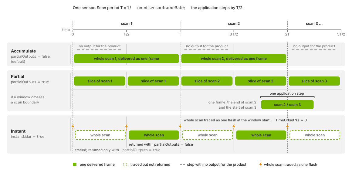
Which steps return a frame: only the completing step with
partialOutputs false; every step with it true, a window that crosses a
scan boundary carrying the end of one scan and the start of the next; with
instantLidar a whole scan flashed at the
start of every step, returned on every step or only on the completing one
as partialOutputs decides.#
With partialOutputs = false (default), the model accumulates a complete
scan and returns it on the step that finishes it. timestampNs is the
scan’s start. Intermediate steps provide no output; see
steps without completed scans
and Sensor Scheduling. The completing step’s output settings
apply to the entire scan, including points traced before a runtime edit.
The parameters report those settings.
With partialOutputs = true, each step delivers its portion of the scan,
with a timestamp at that frame’s start. The consumer accumulates the scan if
needed. A frame crossing a scan boundary contains the end of one scan and
the start of the next. See Sensor Scheduling for choosing a
delivery policy and its relation to scan rate.
With instantLidar = true, the entire pattern fires at the start of each
step’s interval. partialOutputs controls which steps return that scan.
See USD Attributes for scheduling details and
instant lidar for uses and limitations.
For a returned interval [S, T], timestampNs is S and every
TimeOffsetNs is zero. Start/end parameters retain S, T and their
endpoint poses. COMPENSATED output also references S; the flash
contains no within-scan motion to remove.
The frame counter counts rendered frames, not delivered scans. frameId
advances with every frame the model renders, including the mid-scan frames
that deliver nothing with partialOutputs false. A live edit that only
rebuilds the model’s buffers, such as a change to maxReturns, keeps the
counter running; whether a scan being accumulated survives such an edit is on
USD Attributes under the runtime-edit rules. A change to what the
RenderProduct requests rebuilds the model instead, and frameId restarts
with it; Runtime Parameter Updates states that rule for every model.