

Tune Noise, Quantization and Confidence#
Goal. Tune depth noise and coverage, using a noise-free run and the model’s confidence map to check the result. Noise and quantization move measurements along image rows; confidence determines which pixels receive them.
Before you start. Set up a depth product that delivers all five outputs
(Set Up a Depth Product). Author the attributes below on its Camera
with OmniSensorGenericDepthSensorSingleViewAPI applied. See
USD Attributes for their units and interactions, and
invalid entries
for what zero means in DepthSensorDistance.
Get a noise-free run#
Set noiseMean to zero:
float omni:sensor:depthSensor:noiseMean = 0.0
A zero step switches quantization and the Gaussian jitter off together,
whatever noiseSigma holds (the noise attributes say why). Every measurement
retains its reprojected pixel position. Use this run to identify missing
measurements caused by occlusion, the range limits
or the confidence test rather than from noise. Setting noiseSigma to zero
on its own is not the same: with noiseMean above zero the disparity is
still quantized.
Shape the noise#
Set noiseMean above zero to enable the stage, then tune the other two
values in the direction you need: raise noiseSigma for more scatter, and
raise noiseDownscaleFactorPixel to move pixels in coarser patches. All
three use rendered-image pixels: the first two measure disparity and the third
sets the spatial scale of the noise. Tune them against the device’s output at
the same resolution; what each one does is on the noise attributes. A run with more scatter than
the defaults, in two-pixel patches, is authored like this:
float omni:sensor:depthSensor:noiseMean = 0.25
float omni:sensor:depthSensor:noiseSigma = 0.5
float omni:sensor:depthSensor:noiseDownscaleFactorPixel = 2.0
The stage changes each measurement’s pixel position along its row while
preserving its distance value. Expected effects include pixels with no assigned
measurement, irregular object boundaries and selection of the nearer sample
when two samples project to the same pixel. These effects vary between frames
even in a static scene. On a slanted surface a displaced
measurement also shows up at a pixel whose own distance differs. The
single-pixel cleanup of outlierRemovalEnabled runs before this stage
(Outputs has the stage order), so it does not fill noise
speckle. Which values match a real device is a tuning question a spec sheet
rarely answers (Build a Profile from a Spec Sheet):
start from the defaults and compare against recordings of the device.
Increase depth coverage#
Once occlusion holes, the near limit and the range limits are accounted for
(Outputs lists the stages that discard a value), an empty
region in DepthSensorDistance is the confidence test at work: the pixel’s
source in the rendered view did not show enough texture. The following three
changes can increase coverage and can be combined.
Give the scene texture or contrast. Add texture to the materials, or light the scene so that surfaces show gradients, before adjusting the model’s attributes: the test measures visible detail in the rendered image, so a flat, evenly lit wall or a region that renders to uniform white or black gives it nothing (the texture term).
Switch on the simulated IR projector. Set effectiveDistance above zero,
in meters: within that distance a surface is accepted whether or not it has
texture, at any threshold above zero (the IR term describes the decrease in
IR confidence beyond that distance). Use this parameter to accept measurements
on untextured surfaces near the camera.
Increase confidenceThreshold to accept more pixels. The applied
threshold decreases nonlinearly as the authored value increases. Adjust the
authored value toward 1 and read the
direction warning and the remap table
before selecting a value. Decrease the authored value to require greater
confidence. A pixel with zero texture confidence requires a positive IR term
to pass.
For a 3 m projector range and permissive confidence, author on the Camera:
float omni:sensor:depthSensor:effectiveDistance = 3.0
float omni:sensor:depthSensor:confidenceThreshold = 0.99
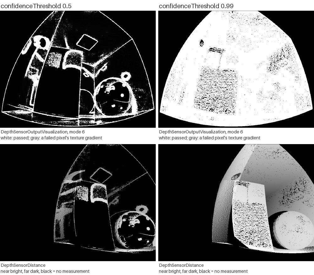
Coverage increases as the applied threshold decreases. Left: the mode 6 confidence map (top) and
DepthSensorDistance (bottom) of a Cornell box test scene’s fisheye depth
product at a confidenceThreshold of 0.5; right: the same two images
at 0.99. White in the confidence map is a pixel that passed and gray the
raw texture gradient of one that failed; black in the distance image is a
zero, no measurement. At 0.5 only edges and highlights pass; at 0.99
nearly the whole view does. The simulated IR projector is off,
effectiveDistance at its default of 0, and noise is off, so the
threshold is the only difference between the columns.#
Verify it worked#
Judge coverage from DepthSensorDistance and from the confidence map, before
and after each change.
Set
rgbDepthOutputModeto6and look atDepthSensorOutputVisualization: a pixel that passed is white, the rest show their raw texture gradient, so a dark area is a surface with too little texture to exceed the applied threshold. With the IR projector disabled, brighter rejected pixels have confidence values closer to that threshold. The other modes are in the mode table.Count the measurements. A zero distance denotes an invalid measurement, regardless of cause and there is no separate validity channel, so filter on a non-zero distance or on the point’s
wcomponent,1for a measurement and0for none (invalid measurements). With the two outputs mapped to the CPU and viewed as NumPy arrays (Sensor Outputs has the mapping call):coverage = (distance[..., 0] > 0).mean() # DepthSensorDistance, (H, W, 1) valid = points[..., 3] > 0 # DepthSensorPointCloudPosition, (H, W, 4)
Render enough frames first. Warm the renderer up before you judge coverage (the warm-up note is under invalid measurements), and compare only frames rendered with the same warm-up. With noise on, compare several frames, because the speckle flickers and one frame overstates or understates coverage; a noise-free run (above) is the cleaner reference for a coverage comparison.
When it goes wrong#
Coverage fell when you lowered confidenceThreshold. A higher threshold
keeps more pixels, not fewer: move toward 1 in large steps and read the
direction warning and the remap table
first.
Speckle is still there with noiseSigma at zero. With noiseMean
above zero the disparity is still quantized; only a zero noiseMean switches
quantization and the jitter off together (above).
An untextured surface stays empty whatever the threshold. No threshold
recovers a pixel with no texture signal at all; only the simulated IR projector
does, effectiveDistance above zero, within that distance (above).
Anything else is on the Symptom Index.