

Configure a Firing Pattern#
A firing pattern defines when each emitter fires and where it points. The Lidar generic core model combines scan scheduling with one or more emitter states to repeat that pattern. This procedure covers rotary and solid-state patterns, validation rules and output checks. See USD Attributes for attribute definitions and Outputs for firing identifiers.
Before you start, configure a sensor and RenderProduct; see Lidar generic core model and Output Configuration.
Pattern authoring#
Scan attributes set the pattern size and repetition rate. Emitter states
provide per-emitter directions, firing times and channel IDs.
OmniSensorGenericLidarCoreAPI includes emitter state s001. Apply
additional instances, s002 and above, to alternate between patterns.
See USD Attributes for definitions of scans, ticks, emitters and channels.
The example configures two emitters and their first state. Each required
array contains numberOfEmitters entries:
#usda 1.0

def OmniLidar "generic_lidar" (
    prepend apiSchemas = ["OmniSensorGenericLidarCoreAPI"]
)
{
    double2 omni:sensor:frameRate = (10, 1)
    float omni:sensor:Core:rotPatternFiringResDeg = 0.1
    uint omni:sensor:Core:numberOfEmitters = 2
    uint omni:sensor:Core:numberOfChannels = 2

    # one entry per emitter, so numberOfEmitters elements each
    float[] omni:sensor:Core:emitterState:s001:azimuthDeg = [0, 0]
    float[] omni:sensor:Core:emitterState:s001:elevationDeg = [-1, 1]
    uint[] omni:sensor:Core:emitterState:s001:fireTimeNs = [0, 1000]
    uint[] omni:sensor:Core:emitterState:s001:channelId = [1, 2]  # any numbering
}
from pxr import Gf, Sdf

generic_lidar = stage.DefinePrim("/generic_lidar", "OmniLidar")
generic_lidar.AddAppliedSchema("OmniSensorGenericLidarCoreAPI")
generic_lidar.CreateAttribute(
    "omni:sensor:frameRate", Sdf.ValueTypeNames.Double2, custom=False
).Set(Gf.Vec2d(10.0, 1.0))
generic_lidar.CreateAttribute(
    "omni:sensor:Core:rotPatternFiringResDeg", Sdf.ValueTypeNames.Float, custom=False
).Set(0.1)
generic_lidar.CreateAttribute(
    "omni:sensor:Core:numberOfEmitters", Sdf.ValueTypeNames.UInt, custom=False
).Set(2)
generic_lidar.CreateAttribute(
    "omni:sensor:Core:numberOfChannels", Sdf.ValueTypeNames.UInt, custom=False
).Set(2)
generic_lidar.CreateAttribute(
    "omni:sensor:Core:emitterState:s001:azimuthDeg", Sdf.ValueTypeNames.FloatArray, custom=False
).Set([0.0, 0.0])
generic_lidar.CreateAttribute(
    "omni:sensor:Core:emitterState:s001:elevationDeg",
    Sdf.ValueTypeNames.FloatArray,
    custom=False,
).Set([-1.0, 1.0])
generic_lidar.CreateAttribute(
    "omni:sensor:Core:emitterState:s001:fireTimeNs", Sdf.ValueTypeNames.UIntArray, custom=False
).Set([0, 1000])
generic_lidar.CreateAttribute(
    "omni:sensor:Core:emitterState:s001:channelId", Sdf.ValueTypeNames.UIntArray, custom=False
).Set([1, 2])
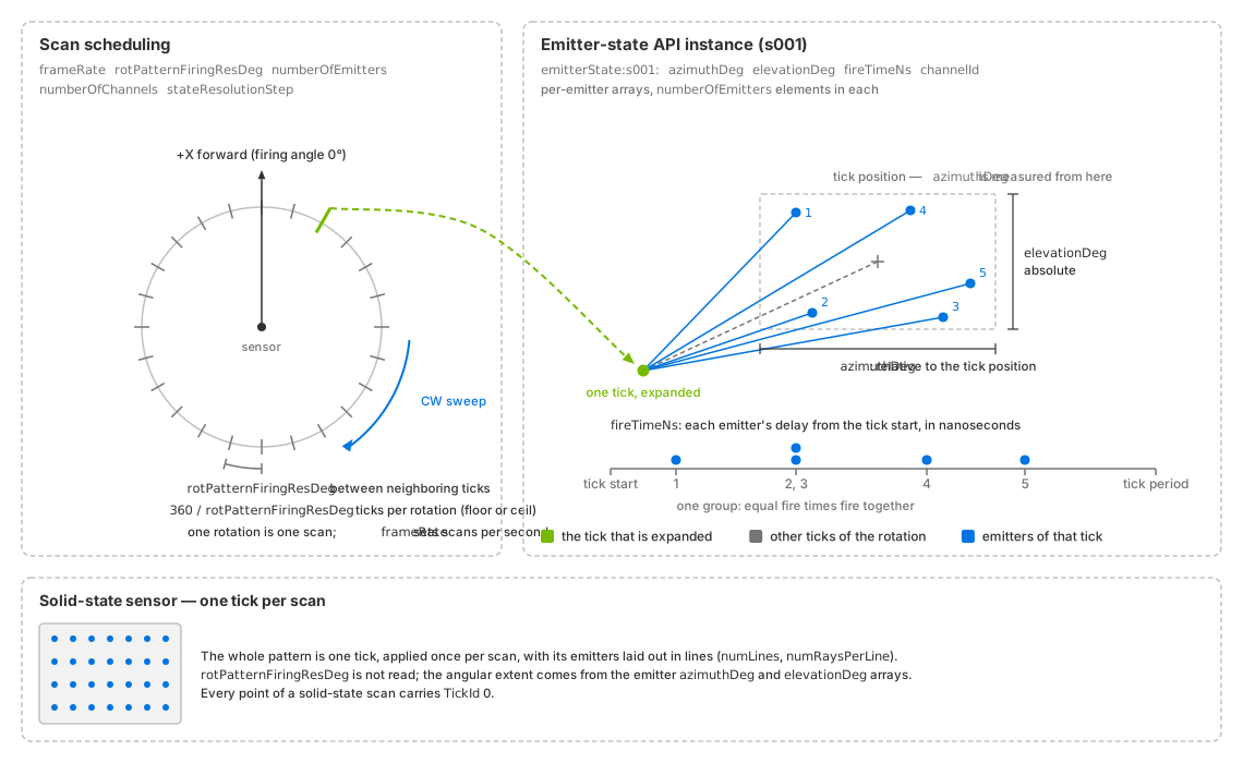
Rotary ticks are spaced by rotPatternFiringResDeg, with frameRate
setting the scan rate. An OmniSensorGenericLidarCoreEmitterStateAPI
instance defines each emitter’s direction (azimuthDeg, elevationDeg)
and firing time (fireTimeNs) within a tick. A solid-state sensor
(lower panel) applies its pattern once per scan.#
Scan scheduling#
omni:sensor:frameRate sets complete scans per second. For rotary scans,
rotPatternFiringResDeg sets the angular step between ticks; solid-state
scans do not use it. numberOfEmitters sets the number of firings per tick
and the length of each required emitter-state array.
numberOfChannels sets the detector count. It can differ from the emitter
count, but solid-state scans require at least numberOfEmitters channels.
stateResolutionStep controls cycling between multiple emitter states.
numLines and numRaysPerLine describe solid-state line patterns.
See USD Attributes and the generated schema reference for types, defaults and constraints.
Scan rate and angular step#
omni:sensor:frameRate controls complete scans per second, while
rotPatternFiringResDeg controls the angular spacing of ticks within each
rotary scan. Together they set the tick rate: on average a rotary sensor fires
frameRate * (360 / rotPatternFiringResDeg) ticks per second. A faster scan or
a finer step therefore shortens each tick, and a pattern’s last fire time still
has to fit inside one tick period (refer to the fire-time rules). With the schema’s defaults, a step of 0.1
degrees, which is 3,600 ticks per rotation, and a pattern whose last emitters
fire 24.5 microseconds into the tick, a rotary sensor fails validation above
about 11.3 Hz, and the renderer logs the reason as an error; what a rejected
parameter set does is under a rejected parameter set.
A rotation does not hold a whole number of ticks unless you choose an angular
step that divides 360. Let q = 360 / rotPatternFiringResDeg. If q is
not a whole number, the model carries the fractional phase across rotations, so
completed rotations contain either floor(q) or ceil(q) ticks while the
long-run firing rate is preserved.
Warning
Allow for ceil(q) ticks when allocating per-rotation storage. If
rotPatternFiringResDeg does not divide 360 exactly, successive rotations
can contain different tick counts. Delivered TickId values are a subset
of [0, that rotation's tick count); they do not report the count.
See Outputs.
Emitter states#
An emitter state is the firing pattern applied at every tick, written as
parallel arrays with one entry per emitter under
omni:sensor:Core:emitterState:s###:. Four arrays are required:
azimuthDeg: the emitter’s azimuth relative to the tick position.elevationDeg: its absolute elevation.fireTimeNs: its firing delay from the start of the tick, in nanoseconds.channelId: the detector it reports into, in any numbering.
Optional per-emitter arrays include:
bank: the line a solid-state emitter belongs to.rangeId: the range window applied to the emitter.vertOffsetMandhorOffsetM: offsets of the emitter’s origin.distanceCorrectionM: a correction subtracted from the reported range, in meters.focalDistMandfocalSlope: arrays checked for length but not used by ovrtx.emitterPeakPowerW: per-emitter peak power, in watts.roi: region-of-interest flags, used with the per-state flagisROIState.
The meaning, units and constraints of each array are on USD Attributes
under the emitter-state attributes. The range windows rangeId selects, and
the region of interest that roi and isROIState take part in, are on
Constrain the Field of View (the range window). The
emitter-origin offsets move both the traced rays and the published points, and
the output coordinates already include them in every output frame; refer to
Outputs before you add an offset of your own.
Rules the model checks#
The model checks the following rules at creation and on every update.
Parameter validation also lists
bounds for bank, rangeId and numRaysPerLine. Run
Sensor Definition Validation to check a layer before rendering.
Each required array — azimuthDeg, elevationDeg, fireTimeNs and
channelId — must contain numberOfEmitters entries. Optional arrays
must be empty or have that same length. An empty optional array disables its
correction for that emitter state. The schema defaults contain 128 entries
in each required array and leave optional arrays empty. Changing
numberOfEmitters therefore requires replacing the required arrays.
fireTimeNs must be nondecreasing within each emitter state. Equal values
define simultaneous firings, which are always processed together in one step.
The final value must not exceed the tick period, including equality. For a
solid-state sensor, one tick spans the entire scan period. A violation rejects
the complete parameter set.
Channel IDs are reported exactly as authored. Across all emitter states,
the number of distinct IDs must not exceed numberOfChannels. Exceeding
it rejects the complete parameter set. See
channel labels for default
numbering and ChannelId
for output behavior, including unwritten entries.
A positive omni:sensor:frameRate must evaluate to at least 0.466 Hz. Lower positive
rates are rejected, because the per-point TimeOffsetNs is a signed 32-bit
nanosecond value and a slower scan cannot be expressed in it. The rule applies
to positive rates only; what a rate of (0, 1) does is under
omni:sensor:frameRate on
USD Attributes.
A failed check rejects the entire parameter set and logs an error. A running sensor retains its previous values, including values for otherwise valid edits in the same update; see update outcomes. Invalid initial parameters prevent initialization until corrected. See runtime restrictions for settings that require model recreation.
Add a second emitter state#
A second emitter state is a second instance of the emitter-state API.
OmniSensorGenericLidarCoreAPI already applies
OmniSensorGenericLidarCoreEmitterStateAPI as instance s001; apply
s002 next to it and author that instance’s own arrays, each with
numberOfEmitters entries. With stateResolutionStep = 1 a rotary lidar
alternates between the two states on every tick, and a solid-state lidar on
every completed scan. The example below adds the second instance and its four
required arrays:
#usda 1.0

def OmniLidar "two_state_lidar" (
    prepend apiSchemas = [
        "OmniSensorGenericLidarCoreAPI",
        "OmniSensorGenericLidarCoreEmitterStateAPI:s002",
    ]
)
{
    uint omni:sensor:Core:numberOfEmitters = 2
    uint omni:sensor:Core:numberOfChannels = 2
    uint omni:sensor:Core:stateResolutionStep = 1

    float[] omni:sensor:Core:emitterState:s001:azimuthDeg = [0, 0]
    float[] omni:sensor:Core:emitterState:s001:elevationDeg = [-1, 1]
    uint[] omni:sensor:Core:emitterState:s001:fireTimeNs = [0, 1000]
    uint[] omni:sensor:Core:emitterState:s001:channelId = [1, 2]

    float[] omni:sensor:Core:emitterState:s002:azimuthDeg = [0, 0]
    float[] omni:sensor:Core:emitterState:s002:elevationDeg = [-2, 2]
    uint[] omni:sensor:Core:emitterState:s002:fireTimeNs = [0, 1000]
    uint[] omni:sensor:Core:emitterState:s002:channelId = [1, 2]
}
from pxr import Gf, Sdf

two_state_lidar = stage.DefinePrim("/two_state_lidar", "OmniLidar")
two_state_lidar.AddAppliedSchema("OmniSensorGenericLidarCoreAPI")
two_state_lidar.AddAppliedSchema("OmniSensorGenericLidarCoreEmitterStateAPI:s002")
two_state_lidar.CreateAttribute(
    "omni:sensor:Core:numberOfEmitters", Sdf.ValueTypeNames.UInt, custom=False
).Set(2)
two_state_lidar.CreateAttribute(
    "omni:sensor:Core:numberOfChannels", Sdf.ValueTypeNames.UInt, custom=False
).Set(2)
two_state_lidar.CreateAttribute(
    "omni:sensor:Core:stateResolutionStep", Sdf.ValueTypeNames.UInt, custom=False
).Set(1)
two_state_lidar.CreateAttribute(
    "omni:sensor:Core:emitterState:s001:azimuthDeg", Sdf.ValueTypeNames.FloatArray, custom=False
).Set([0.0, 0.0])
two_state_lidar.CreateAttribute(
    "omni:sensor:Core:emitterState:s001:elevationDeg",
    Sdf.ValueTypeNames.FloatArray,
    custom=False,
).Set([-1.0, 1.0])
two_state_lidar.CreateAttribute(
    "omni:sensor:Core:emitterState:s001:fireTimeNs", Sdf.ValueTypeNames.UIntArray, custom=False
).Set([0, 1000])
two_state_lidar.CreateAttribute(
    "omni:sensor:Core:emitterState:s001:channelId", Sdf.ValueTypeNames.UIntArray, custom=False
).Set([1, 2])
two_state_lidar.CreateAttribute(
    "omni:sensor:Core:emitterState:s002:azimuthDeg", Sdf.ValueTypeNames.FloatArray, custom=False
).Set([0.0, 0.0])
two_state_lidar.CreateAttribute(
    "omni:sensor:Core:emitterState:s002:elevationDeg",
    Sdf.ValueTypeNames.FloatArray,
    custom=False,
).Set([-2.0, 2.0])
two_state_lidar.CreateAttribute(
    "omni:sensor:Core:emitterState:s002:fireTimeNs", Sdf.ValueTypeNames.UIntArray, custom=False
).Set([0, 1000])
two_state_lidar.CreateAttribute(
    "omni:sensor:Core:emitterState:s002:channelId", Sdf.ValueTypeNames.UIntArray, custom=False
).Set([1, 2])
Apply an additional emitter-state API instance for each pattern and author
its arrays under the matching instance name (s003 and so on). States run
in instance-name order, advancing every stateResolutionStep ticks on a
rotary sensor or scans on a solid-state sensor. See
scheduling attributes
for ordering and zero-padding rules. Partial outputs retain the state of their
solid-state scan. Each point’s TickState reports the
zero-based index of the state that fired it.
Solid-state timing#
A rotary sensor distributes its pattern over the rotation, one tick per angular step. A solid-state sensor has one tick per scan and processes its pattern in fire-time order, one window per simulation step.
Scan boundaries occur at omni:sensor:startTime plus whole scan periods.
Fire times are relative to the scan’s start. The window rules are:
Include its start and exclude its end. A group on a boundary between steps fires in the later step only.
The window that closes a scan also includes a group exactly at the scan’s end; validation permits that fire time.
A window containing no fire times fires nothing, including after the last group.
For a flash lidar, give every emitter the same fireTimeNs. They form one
group that fires in the step containing that time. ovrtx splits a step crossing
a scan boundary into one window per scan, so each group fires once per scan.
With instantLidar = false, the scan completes and its emitter state
advances when the step reaches the period boundary, even if no emitter fires
in that step. With instantLidar = true, the whole pattern fires at each
traced window’s start and completes a scan. Authored firing times are ignored
during tracing but remain subject to validation; see
instant lidar.
partialOutputs controls delivery independently. By default, only the
completing step returns the scan; see
steps without completed scans.
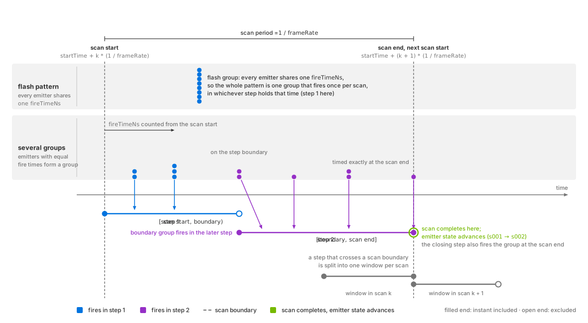
A solid-state scan over two simulation steps. Each step fires the groups inside its window, start included and end excluded, so the group on the shared boundary fires in the second step; the step whose window reaches the end of the scan period completes the scan and advances the emitter state.#
Verification#
Request TickId and ChannelId on the PointCloud RenderVar, and
EmitterId too on a solid-state sensor, run the sensor, and read the
delivered entries [0, Counts[0]), selecting the real returns by the
Flags valid bit, as Sensor Outputs describes under
reading a variable-size output.
What each channel means is on Outputs. Three things must hold:
Every valid point’s
ChannelIdis one of the ids authored in the emitter states’channelIdarrays, unchanged, so no more thannumberOfChannelsdistinct values appear.On a rotary sensor, accumulated over one completed rotation, every
TickIdis below that rotation’s tick count (fractional ticks). A tick that found nothing contributes no point, so the distinct values are a subset of that range and never wider than it.On a solid-state sensor every
TickIdis0, one tick per scan, so check the schedule withEmitterIdinstead: withpartialOutputsoff andincludeInvalidPointson, every scan the sensor traced in full carries eachEmitterIdfrom0throughnumberOfEmitters - 1, each exactly once whennumberOfChannelsequalsnumberOfEmittersandmaxReturnsis1.
Return counts depend on scene geometry and filtering. Each channel can
produce up to maxReturns returns, and invalid points are dropped by
default. Check tick and channel bounds independently of the valid-return count.
With partialOutputs = false (default), the model accumulates a complete
scan; with true, the consumer accumulates it across frames.
See output timing.
Potential issues#
Per-rotation buffers overrun or come up one tick short: a fractional
qwas read as a fixed tick count. Refer to fractional ticks.Points attributed to the neighboring detector: the consumer reads
ChannelIdas a zero-based index. The output is the authored id; refer to channel ids.An emitter state appears to be ignored: the extra state’s API schema instance is not applied to the prim, or its arrays are authored under a prefix that does not match the instance name. Refer to the emitter-state cycle.
A parameter update or scan rate is rejected: check pattern constraints, including the minimum scan rate. Run Sensor Definition Validation to identify the cause. Invalid initial parameters prevent output; see rejection behavior.
More symptoms, with their causes and remedies across every model, are in the Symptom Index.