

Configure Lidar Output#
The Lidar generic core model can report Cartesian or spherical coordinates in a sensor, world or custom frame. It can deliver complete scans or partial outputs during a scan. Configure both on the sensor prim; output parameters identify the coordinate settings used for each frame.
Before you start, see Output Configuration for requesting outputs and Sensor Outputs for reading them.
Note
The attribute names on this page are the Lidar generic core model’s
omni:sensor:Core:* set. The Lidar generic wpm model carries all of them
under omni:sensor:LidarWpm:*, not always with the same type; the Radar
generic wpmDmat model carries the coordinate system, the frame of reference
and the custom transform under omni:sensor:WpmDmat:*. Refer to their USD
attributes pages: Radar generic wpmDmat model
and Lidar generic wpm model.
Output controls#
The following example configures Cartesian world coordinates, drops invalid
entries and delivers complete scans (partialOutputs = false):
#usda 1.0
def OmniLidar "Lidar40" (
    prepend apiSchemas = ["OmniSensorGenericLidarCoreAPI"]
)
{
    # A full scan completes in each 1/40-second simulation step.
    double2 omni:sensor:frameRate = (40, 1)
    bool omni:sensor:Core:partialOutputs = false
    bool omni:sensor:Core:includeInvalidPoints = false
    token omni:sensor:Core:elementsCoordsType = "CARTESIAN"
    # World-space points let both scans share the camera's viewpoint.
    token omni:sensor:Core:outputFrameOfReference = "WORLD"
    # Keep the emitter firing sequence shorter than each angular tick.
    float omni:sensor:Core:rotPatternFiringResDeg = 1
    double3 xformOp:translate = (-150, 150, 300)
    uniform token[] xformOpOrder = ["xformOp:translate"]
}
from pxr import Gf, Sdf, UsdGeom

lidar = stage.DefinePrim("/World/Lidar40", "OmniLidar")
lidar.SetMetadata("apiSchemas", Sdf.TokenListOp.Create(prependedItems=["OmniSensorGenericLidarCoreAPI"]))
# Rational Hz: numerator / denominator. Each scan takes one 1/40-second step.
lidar.CreateAttribute("omni:sensor:frameRate", Sdf.ValueTypeNames.Double2).Set(Gf.Vec2d(40, 1))
lidar.CreateAttribute("omni:sensor:Core:partialOutputs", Sdf.ValueTypeNames.Bool).Set(False)
lidar.CreateAttribute("omni:sensor:Core:includeInvalidPoints", Sdf.ValueTypeNames.Bool).Set(False)
lidar.CreateAttribute("omni:sensor:Core:elementsCoordsType", Sdf.ValueTypeNames.Token).Set("CARTESIAN")
# World-space points let both scans share the camera's viewpoint.
lidar.CreateAttribute("omni:sensor:Core:outputFrameOfReference", Sdf.ValueTypeNames.Token).Set("WORLD")
lidar.CreateAttribute("omni:sensor:Core:rotPatternFiringResDeg", Sdf.ValueTypeNames.Float).Set(1)
UsdGeom.Xformable(lidar).AddTranslateOp().Set(Gf.Vec3d(-150, 150, 300))
With includeInvalidPoints = false, point arrays contain valid returns
only. With true, all slots are delivered; use Flags to identify valid
entries. See USD Attributes for types, allowed values and defaults of
these controls, outputMotionCompensationState,
customFrameOfReferenceTrafo and instantLidar.
Coordinates and reference frame#
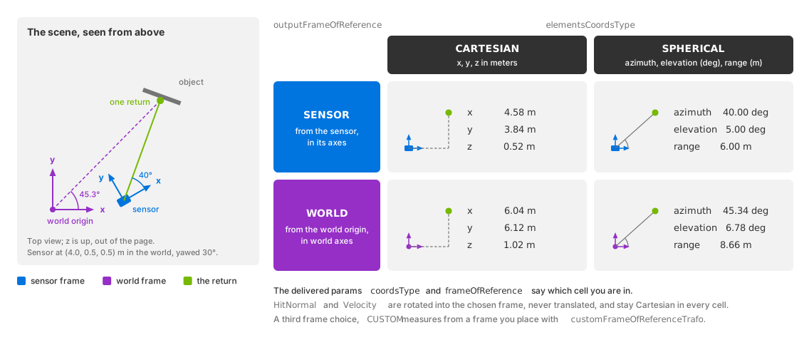
One return, two independent choices: elementsCoordsType picks the
components, outputFrameOfReference the frame they are measured in. The
values alone do not say which combination you are holding; the
coordsType and frameOfReference params do. The values are
illustrative.#
elementsCoordsType selects Cartesian or spherical Coordinates.
outputFrameOfReference selects the sensor, world or custom frame. For
CUSTOM, customFrameOfReferenceTrafo defines the frame with a
six-element transform.
outputMotionCompensationState independently controls correction for sensor
motion during the scan; see Motion Artifacts. Reference-frame and
compensation settings also transform HitNormal and Velocity. These
vectors remain Cartesian regardless of elementsCoordsType and are
rotated without translation. See Outputs for channel definitions.
Runtime updates#
Coordinate type, reference frame, custom transform, compensation,
includeInvalidPoints and partialOutputs support runtime updates.
Frames already in flight retain their previous settings.
With partialOutputs = false, the model retains raw sensor coordinates
until the completing step. It then transforms all points using that step’s
coordinate type, reference frame, custom transform and compensation state.
A mid-scan edit to these settings applies to the entire delivered scan,
including points traced before the edit.
See Runtime Parameter Updates for update and rejection behavior.
scanType and rayType require recreation; see USD Attributes.
Output parameters#
Read the output parameters to identify the settings used for each frame. The verification procedure uses them to check that edits took effect.
Delivery cadence#
partialOutputs controls scan delivery. instantLidar changes tracing
to a simultaneous flash:
With
partialOutputs = falseandinstantLidar = false(defaults), the model accumulates a scan and returns it on the completing step. Intermediate steps return no output for the product.With
partialOutputs = true, each advancing step returns its portion of the scan. A window with no firing still returns an output withCounts[0] = 0. A window crossing a scan boundary includes the end of one scan and the start of the next. Output rate can exceed scan rate.With
instantLidar = true, each trace produces a complete scan.partialOutputsselects which steps deliver it, as described below.
omni:sensor:frameRate sets complete scans per second as rational Hz.
See Sensor Scheduling for its relationship to simulation
steps and delivery policy.
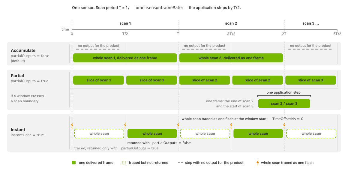
Each application step spans half the scan period set by
omni:sensor:frameRate:#
Accumulated output: returns a complete scan every second step, with no output on intermediate steps.
Partial output: returns the points captured during each step. A step crossing a scan boundary includes points from both scans.
Instant lidar: traces a complete scan at each step’s start time.
partialOutputs = truereturns it every step;falsereturns it only when the step completes a scan period.
Steps without completed scans#
With partialOutputs = false, output is returned only when a step
completes a scan period. Intermediate steps omit the product or return it
with an empty frame list. This is expected.
Iterate the products and frames actually returned. Request the product on
every step: omitting it discards the accumulated scan; see
Sensor Scheduling. When a frame
arrives, bound each per-point read by Counts[0] as described in
Sensor Outputs.
Instant lidar#
instantLidar traces a complete scan as one flash at the step’s start
time and pose. All firings are simultaneous. partialOutputs controls
which steps return the complete scan.
With partialOutputs false, the default, ovrtx schedules the sensor in frames
of one scan period exactly as for an accumulated scan, so the whole scan is
returned only on the step that completes the period, and the flash traced on a
step in between is not returned. Author partialOutputs = true to receive a
whole scan on every step that advances time, or step at the scan period, which
makes every step a completing one.
Warning
Instant lidar suits a demonstration, a unit test or a first look at a scene. It is not representative of a time-resolved scan: nothing in the scan takes time, so a result obtained with it does not transfer to a sensor scanning in real time. Do not validate motion handling or timing with it.
Which steps flash, the zero-length-window rule for each scanning principle included, and that validation still checks the authored fire times, are on USD Attributes; an advancing first step flashes at time zero.
The frame reports the window’s start as its timestampNs and every point
carries a TimeOffsetNs of 0; what the frame-start and frame-end params and
COMPENSATED output do under instant lidar is on the Outputs page. Without motion BVH the start pose the flash uses is the frame-end
pose, as Motion Artifacts explains.
Channel selection#
Use the PointCloud RenderVar’s channels list to request channels.
See channel selection
for automatically included channels and unrecognized names, and
Outputs for available channels, types and shapes.
Verification#
Check the frame parameters before interpreting its arrays. coordsType,
frameOfReference and motionCompensationState report the settings used.
After an edit, read a newly produced frame; frames already in flight retain
the old values. A persistent mismatch can mean the attributes are not reaching
the model or the parameter set was rejected. Check these causes before
investigating the consumer.
To check delivery timing:
Set
partialOutputs = false.Step at half the scan period.
Check that complete scans arrive every second step, with no output for the product on intermediate steps. Use a scene that produces detections to check for a non-zero
Counts[0]on completed scans.
This applies to rotary and solid-state sensors. Solid-state scans are returned at the end of the scan period, regardless of the emitter fire times; see Configure a Firing Pattern. Point counts can vary between runs; check the delivery timing rather than an exact count.
The lidar example prints
one summary per run:
valid points=..., mean intensity=..., max time offset=... ns.
A non-zero count confirms that a scan produced points; this run-level summary
does not show the delivery timing of individual steps.
Potential issues#
Coordinates do not behave like Cartesian positions:
elementsCoordsTypeis at its default,SPHERICAL, and the consumer assumedCARTESIAN. Set it explicitly rather than relying on the default being what you expect.Points sit in a sensible shape but in the wrong place, or move when the sensor moves and should not:
outputFrameOfReference. Refer to Motion Artifacts when the sensor is moving.The custom transform has no effect:
customFrameOfReferenceTrafois read only whenoutputFrameOfReference = CUSTOM. Its six values arex,yandzin meters followed by roll, pitch and yaw in radians, so a rotation authored in degrees lands far from where you meant it.A value authored on a running sensor changes nothing: read the params of a later frame, because the frame in flight when you authored it keeps the old value. If the params never change, the whole parameter set was rejected. A running sensor keeps its previous values and output layout, and the reason is logged as an error; Sensor Definition Validation names the cause before you render. One sure cause is an edit to
scanType: it cannot change on a running sensor, so an update that changes it is rejected whole. Recreate the sensor to change the principle; the model’s USD attributes list what else stays fixed and what happens to the rejected value.Some steps deliver no points, or no output for the product at all: refer to a mid-scan step.
An instant lidar delivers on some steps only:
partialOutputsis false and your step is shorter than the scan period, so the flash traced on a step that does not complete the period is not returned. AuthorpartialOutputs = trueor step at the scan period; refer to instant lidar.A channel you expected is absent from the mapped output: it was not listed in the RenderVar’s
channels. Refer to channel selection.