

Tutorials#
These tutorials derive Lidar generic core model profiles from manufacturer specifications. Each includes a completed USD layer you can reference into a scene, the source of each parameter and checks against the device’s published behavior. See Lidar generic core model for model capabilities and How-To for individual configuration tasks.
See Build a Profile from a Spec Sheet for the profiling method.
Tutorial profiles#
Parameterize a Rotary Lidar: Velodyne Alpha Prime derives a 128-channel rotary profile from the
manual’s nominal channel angles and firing sequence, including maintenance
gaps. It relates RPM, frame rate and rotPatternFiringResDeg so changes
preserve the firing rate. The resulting layer is
Velodyne_Alpha_Prime_Rev4.usda.
Parameterize a Solid-State Lidar: Blickfeld Cube 1 derives a solid-state MEMS pattern from the
manufacturer’s mirror equations. It calculates 5,850 directions and firing
times and documents four conflicts in the published specifications. It
includes Blickfeld_Cube1_Analytic.usda and
generate_blickfeld_cube1_profile.py for regenerating the pattern.
Parameterize One Sensor Two Ways: SICK TiM781 models a single laser and detector scanning 811 directions
over 270 degrees at 15 Hz. SICK_TiM781.usda uses a rotary emitter;
SICK_TiM781_SolidState.usda uses 811 explicit directions and firing times.
The rotary schedule scales with scan rate. The solid-state timing must be
regenerated when the rate changes.
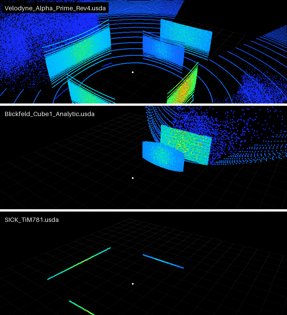
The three shipped profiles referenced into the panel scene at one mount, one
below the other, each scan shaded by Intensity: the Alpha Prime’s
128-line rotary sweep, the Cube 1’s Lissajous frame of 5,850 pulses on the
pane ahead and the wall behind it, and the TiM781’s single 270-degree plane,
which meets only the panels at its height. The layers are
Velodyne_Alpha_Prime_Rev4.usda, Blickfeld_Cube1_Analytic.usda and
SICK_TiM781.usda under tutorials/assets/.#
Configuration topics#
Each tutorial identifies its sources using source-confidence categories, derives a profile, references it into a scene and validates it. Checks cover parameter acceptance, geometry, timing, range, intensity and comparison with real captures. The following pages explain individual configuration tasks:
Configure a Firing Pattern: the emitter array lengths, the fire-time order, fractional ticks, channel ids and the minimum scan rate.
Constrain the Field of View: the azimuth window and the range band.
Tune Intensity and Point Drops: divergence versus waist and point drops.
Configure Lidar Output:
partialOutputs, scan completion and steps that deliver no points.Motion Artifacts: the motion BVH and the compensation state and the compensation tokens.
USD Attributes: attribute namespaces, the scan type, the parameter validation, range accuracy versus resolution and why channel ids are labels.
Outputs: reading the points back,
Counts, the valid entries and the channel layout.Sensor Definition Validation: the introspection parameter validation.
Output Configuration: the RenderProduct and RenderVar each profile layer carries.
Reading order#
For rotary sensors, start with Parameterize a Rotary Lidar: Velodyne Alpha Prime. For solid-state patterns, start with Parameterize a Solid-State Lidar: Blickfeld Cube 1, including its treatment of conflicting sources. Parameterize One Sensor Two Ways: SICK TiM781 compares both representations on one device.
Each layer includes an OmniLidar and a RenderProduct requesting
PointCloud. The tutorials show how to reference the default prim, select
channels, validate the layer before rendering and compare the results with
measured data.
Note
The profiles are documentation-derived baselines, not certified digital twins of a particular hardware unit. Each contains what can be copied or reasonably inferred from the public manuals. Behavior those sources do not define, such as unit-specific optical power, receiver response and thresholds, noise, corrections and the intensity transfer, stays generic or approximate and has to be tuned against measured sensor data for higher-fidelity use.